TDF Flange Forming Machine Overview

Usage, performance and features
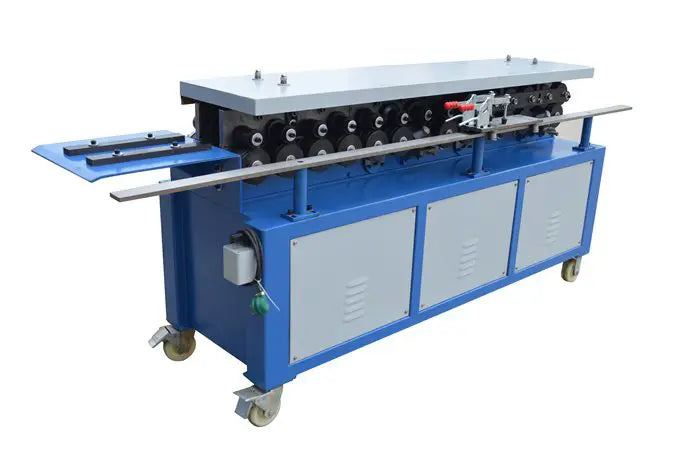
TDF flange forming machine is mainly used to produce square and rectangular air ducts and self-made semi-finished TDF flanges. It can also be used to create finished ducts by combining it with a duct production line, cutting machine, bending machine, locking machine and corner code machine.
Our company offers two types of TDF flange forming machines: T12 and T15. The thickness of the formed iron plate varies from 0.5mm to 1.5mm. These machines are ideal for on-site manufacturing of ventilation exhaust ducts in industries such as mining, hotels, shopping malls and construction due to their compact size, lightweight design, ease of movement, adjustment, ease of operation and reliability.
Following are use case diagrams.
Here are the drawings:
TDF flange installation
Basic Parameters
Components of TDF flange forming machine: The machine consists of a rack, a transmission component, a flange forming component, a hook forming component and a power component (motor and reducer).
Overall dimensions: The machine measures 2,700 mm long, 700 mm wide and 1,100 mm high.
Weight: The machine weighs approximately 850 kilos.
Reducer model: The machine uses an RV110 reducer with a gear ratio of 25-30.
Engine power: The engine has a power of 3 kW.
Applicable material: The machine is designed to work with common galvanized plates with a thickness of 0.6mm to 1.2mm.
Working Speed: On average, the machine operates at a speed of about 14 meters per minute.
Length limitation: There is no limit to the length of material that can be processed by the machine.
Product accuracy: The size error does not exceed ±0.6mm and the angle error does not exceed ±2 degrees.
Model and Technical Parameters
Table 1:
| Model | Motor
(KW) |
Plate Thickness
(mm) |
Form | size “a”
(mm) |
Weight
(kg) |
Dimension (LWH) |
| T-12 | 3 | 0.5-1.2 |
|
35±0.5 | 850 | 2700×700×1100 |
table 2

The corner of the duct is processed using a pair of corner molds, one set for cutting and the other for press molding. The process is carried out using a 40T punch, although a 25T punch can also be used to process corners of T-10 DC type ducts.
Regarding the hook code cutting size, the width is 60mm and the slat thickness is 1.0mm. The machine is equipped with a coil slitting machine, eliminating the need for separate slitting.
Working condition
The maximum altitude must not exceed 2,000 meters.
The ambient temperature must vary between -10°C and +40°C.
When the temperature is +40°C, the relative humidity should not exceed 50%. When the temperature is +25°C, the relative humidity should not exceed 90%.
Atmospheric conditions must be free from hazardous substances that could cause explosions and must not contain conductive gases or dusts that can corrode metals or damage insulating gases.
The power requirements are as follows: the voltage must be between 342-418V and the three-phase power imbalance voltage must be controlled in a range where the negative and zero sequences do not exceed 2% of the sequence. The frequency should be between 49.5-50.5.
Configuration and Structure
The T12 TDF forming machine is composed of a bench, a transmission section and a forming section. The contour dimensions can be seen in the attached figure (Fig. 1).
Rack and bench for TDF flange forming machine
The rack is a welded shell made of national standard 8# channel, which is sturdy and reliable. The entire transmission section, forming section and reducer are installed in the housing. The end of the side plate is fixed to the table panel with a horizontal adjustment channel positioning plate on the panel.
Transmission part
The entire transmission system consists of a turbine box that is driven by a turbine reducer with a gear ratio of 30:1 (or other ratios), powered by a 3 kW national standard engine. The reducer drives two drive shafts via sprockets and a chain, and the drive shaft gears drive the transport shaft. The movement of the entire system is then driven by multiple transit gears.
Forming pieces
Both sides of the forming components are composed of 14 rollers, with one side forming flanges and the other side forming hooks. The forming rolls are constructed from GCr15 bearing steel that has undergone heat treatment and salt bath finishing, making them durable.
Shafts and gears are heat treated to ensure their performance and longevity. Each tail has an adjustable device to ensure the flange is aligned to the required specifications.
The side plate is made of forged steel and has been finished. The TDF flange forming machine has 14 groups of forming shafts, each equipped with a driving gear and left and right rollers. The left side consists of the hook roller group, while the right side contains the flange roller group. Furthermore, the right side flange forming component has a rubber material holding wheel and a feeding carriage to ensure stability during the forming process and produce qualified products.
Matters need attention
- On the upper side plate of the TDF flange forming machine, there are double-ended pins ④ and disc springs, which allow automatic adjustment of the gap between the upper and lower rollers based on the thickness of the bearing. For example, in the T-12 machine, the plate thickness is between 0.6-1.2 mm.
- All new flange machines are adjusted and meet qualifications before leaving the factory. If necessary, only the power supply board needs to be adjusted. The four pins ③ and ④ must not be easily adjusted or moved.
Lifting and Installation of TDF Flange Forming Machine
Ensure that no components are lost or omitted during transportation. Carefully inspect all relevant parts to confirm they are complete and undamaged before installation.
Before lifting the machine, carefully check the lifting device to ensure it meets the requirements. Use at least two slings of equal length during the lifting process. Keep the tip of the lifting hook in the center position and maintain a good center of gravity to prevent the machine from losing balance and tipping over. When unloading, place the machine slowly on level ground, with all four feet touching the ground first and no one hanging in the air. Use supports if necessary. The machine must not be tilted or placed at an angle, as this may cause deformation and affect its operation.
The machine must be installed on level, hardened ground.
Assemble a suitable power supply (with suitable voltage, phase and frequency, etc.) and ground wire according to the requirements. Install the electrical system according to the standard color code.
Flange forming machine lubrication
Lubrication in accordance with the following requirement:
| No. | Lubrication Parts | Lubricant | Lubrication time |
| 1 | Transmission gear and chain | Grease | Every 40 hours of work |
| two | Ball bearing and plain bearing | Grease | Every 40 hours of work |
| 3 | Drive chain wheel | Light lubricating oil | Every 80 hours of work |
| 4 | Drive chain wheel | Light lubricating oil | Apply lubricant to the drive chain |
| 5 | Speed reducer | gear oil | Change the oil once every three months |
Adjustment and Operation
Check before turning on the machine
Fill the machine with grease or lubricating oil as needed.
Thoroughly inspect each part, including the tension chain, drive belt tension, leak guard, and mounting bolts, to ensure all parts are in good condition.
Idle work for several minutes to inspect the machine's operating condition
- Inspect the running direction of the TDF flange forming machine and adjust it if it is incorrect.
- Examine all fasteners and tighten any that are loose to eliminate any safety hazards.
- Listen carefully for unusual noises.
- Apply lubricating oil or grease to all bearings, gears, drive shafts and bolts.
- Check the safety and reliability of the electrical system.
- Make sure the protective shield is secure and reliable.
The use of an auxiliary feeding cart depends on the width of the plate and flange.
When the board length is less than 180 mm, it is necessary to use a feeding cart. The plate is placed on the cart, fixed with two clamps and pushed by workers during the rolling process.
If the length of the plate is greater than 180 mm, the cart can be disassembled from the side and stored in a suitable location.
During the first use, measure and evaluate the results. If there is unequal clearance on both sides, adjust the position of the stop plate and the parallelism between the material guide plate and the feeding direction.
If the large right-angled edge of the flange exceeds 90°, lower the clamping rubber wheel to increase the clamping force. If the flange is curving up or down, adjust the shape adjustment wheel accordingly.
Please note that this machine is designed for bend forming and should not be used as a casting mill.
Therefore, a certain gap (approximate plate thickness plus 0.1-0.2mm) is required between the upper, middle and lower rollers, the gap has been adjusted before leaving the factory, users should not arbitrarily turn the screws. countersunk head ③set screw ④ and disc spring (see figures 2 and 5)

Figure 5
If the gap between the rollers varies due to loose screw nuts ③ and screws ④ or other reasons, adjust as follows:
Loosen all nuts ④ and place a plate with the same thickness as the gap between the rollers. Adjust screw ③ until the gaps between four-sided rollers are almost equal. Then tighten the nut ④ (δ=Minimum plate thickness + 0.1-0.2). If you want the minimum gap between the boards, leaving a small gap is acceptable.
Bone shape adjustment
To accommodate sheets of varying widths or thicknesses, loosen the screws on the input positioning plate and move the plate in a direction parallel to the slot. Then tighten the guide plate.
If the plates are thin during flange production and the flange side hook size is insufficient, adjust the flange side feed plate slightly inward.
Security Technology
The TDF flange forming machine must be operated by a professional operator who is fully familiar with the structure and performance of the machine and who has received appropriate training. The operator must strictly follow safety operating procedures. If several operators are involved, one professional must be responsible for directing production.
Regularly inspect the TDF flange forming machine, including its condition, grounding resistance and leakage protection, to ensure that all electrical circuits and components are in safe working condition.
Before performing maintenance or inspection, power must be turned off and the key removed and locked.
The supply voltage must not exceed the nominal voltage by more than 10% to avoid degradation of electrical insulation.
No repairs or adjustments should be made while the machine is in operation.
It is prohibited to touch the rotating rollers, chains and gears with your hands.
If any abnormal sound or odor occurs, immediately stop the machine and solve the problem.
The machine's protective cover must be intact. An incompletely assembled machine cannot be put into production.
Machine maintenance and care
Before carrying out maintenance on the machine, maintenance personnel must be familiar with its performance, specifications, safety measures, mechanism positions and functions, mechanical, electrical and transmission theories, as well as the relationship between order and sequence of action and operational procedures.
Grease or lubricating oil must be added before each shift in accordance with lubrication requirements.
It is prohibited to form sheets with welding scars, burrs or very thick sheets.
Shock, moisture and dust protection considerations must be taken into account for motor, electrical and control components. During the rainy season, if the machine is not used for a long period of time (more than a month), the motor and electrical insulation must be checked and dehumidified before use.
Make sure all exposed hoses and wires are intact.
Keep the roller surface clean and remove impurities and iron debris in a timely manner to extend the service life of the machine.
Establish an equipment file and create a regular maintenance plan, including maintenance logs and logs.
At the end of each shift, clean up any debris, remove iron and dust, turn off the power and lock the machine.
Matters need attention
The TDF flange forming machine has an input voltage of 380V, and the input power socket must have a suitable grounding line to ensure safety.
The shared ball bearings in the TDF flange forming machine have been fully lubricated and generally do not require special care. However, when using the machine for the first time, apply a small amount of oil to the inside of the side plate. Measures must be taken to prevent iron debris from falling into the bearings and affecting their useful life.
The machine uses open drive and lubricating grease must be regularly applied to the gear teeth.
Remove iron debris that falls on the gear and rollers and lubricate the roller surface as necessary.
During the rolling process, as the pieces are gradually formed, it is prohibited to retract the sheet after reaching the fifth roll. If it is necessary to remove the material, loosen the nut ④ and lift the beam ⑥, then retract the material. Otherwise, the machine may be damaged.
To replace accessories, specify the machine model, the year and month of manufacture or purchase, and the factory number marked on the machine or in the user manual. So you can get the accessories from our factory or factory agents.