1. Main Applications and Scope of Use
W12 four-roll plate bending machine is used to bend and form metal plates. It is ideal for creating shapes such as cans, arches and other configurations. The machine is capable of completing the bending process in one feed and also offers ample correction opportunities.
This machine is commonly used in various industries, including shipbuilding, boiler manufacturing, aviation, bridge construction, hydropower generation, chemical production, metal structure manufacturing and machine production.
2. Main Technical Parameter
Here are the specs:
Technical data of four roller plate bending machine
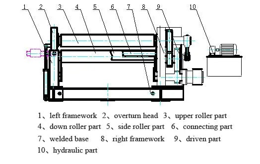
3. Main Structure
3.1 Main Structure
W12 four-roll plate bending machine is designed for bending and shaping metal plates. The machine consists of an upper roller, a lower roller and two side rollers. The upper roller is the main roller and is fixed in place, while the lower roller and side rollers are driven by hydraulic oil.
The bottom roller and side rollers move up and down through hydraulic action, while the center bearing of the upper roller can also be turned and restarted through hydraulic action. Bearings and hydraulic oil tank are located on both sides of the machine frame.
The machine structure is made up of two welded steel components that are installed on a welded base. All operations are controlled from one console.
This machine is widely used in industries such as shipbuilding, boiler, aviation, bridges, hydroelectricity, chemicals, metal structures and machine production.

A four-roll plate bending machine has several advantages over a three-roll plate bending machine. Firstly, it can perform final pre-bending without the need for additional tools or molds, resulting in a smaller straight edge. Secondly, compared to an asymmetrical three-roll bending machine, it can bend the sheet metal without having to rotate it, making the process more efficient and ensuring a higher quality end product.
Another benefit of the four-roll plate bending machine is its user-friendly operation, which reduces the operator's physical effort and makes it easier to use.
In conclusion, the four-roll sheet metal bending machine is a versatile and efficient solution for sheet metal forming jobs, offering several advantages over its three-roll counterpart.
3.2 Main Driven Structure
The upper roller of the four-roll sheet metal bending machine is the driving roller, which is driven by a hydraulic motor. This motor uses a 5:1 gear reduction system, ensuring the upper roller moves at a speed of 4 meters per minute. This allows the machine to complete the feeding process efficiently.
3.3 Wizard-Driven Structure
The bottom roller and side rollers of the four-roll sheet metal bending machine are controlled by a hydraulic device. This device allows the bottom roller and side rollers to move up and down in a timely manner and also allows separate up and down movements.
3.4 Folding Crafts
The four-roll sheet metal bending machine offers a variety of bending techniques, allowing the user to choose the one that best suits their needs. A reference drawing is provided for reference purposes.

(1) To operate the machine, first increase the distance between the upper roller and the lower roller to be a little larger than the thickness of the plate. Then adjust the feed side roller so that the distance between the upper and lower rollers is equal. Finally, position the other side roller between the upper and lower roller.

(2) Feeding: The plate is fed horizontally into the machine until the end of the plate completely touches the center side roller. Then the side roller is lowered to its original position.
(3) Clamping: The plate is securely clamped and pre-bending begins.

(4) Pre-bending: The center side roller is used to pre-bend the other side of the board. After completing pre-bending on the left side, the rear side roller is lowered to its original position. The upper roller is then used to bend the plate to the desired position, as indicated in the drawing. Once the top roller stops, the center side roller is lifted to bend the other side of the plate.

(5) Main Bending: The center and rear rollers are adjusted to the appropriate position, and the upper roller is used to perform the main bending.
(6) Figure bending: The center and rear rollers are adjusted to the appropriate position, and the upper roller is used to realize figure bending.

(7) Removing the workpiece: After completing the bending process, the lower roller is lowered to its lowest position. The workpiece is then gradually lowered to a suitable position with the help of the two side rollers. The machine head is turned and the workpiece is lifted, ensuring it is level with the upper roller before being removed.
4. Hydraulic System
The movement of the bottom roll and side rolls, as well as tipping and readjustment, in the four-roll bending machine are driven by a hydraulic oil tank and controlled by an electromagnetic directional valve switch.
4.1 Hydraulic System Adjustment:
4.1.1 Pump Source Adjustment:
4.1.2 Before starting or restarting the machine after a long period of inactivity, the user must let the oil pump run for 5 minutes to allow it to empty. When starting or stopping the machine, the oil pump must be unloaded.
4.1.3 The pressure of flood valves 10 and 12 must be adjusted to 20 Mpa. When adjusting the flood valve 10, the 1DT and 2DT must be powered electrically or manually using a pin to avoid failure of the electromagnetic valve. When adjusting flood valve 12, the engine must be adjusted while under load. If the engine is running without load, the pressure will be 0.
4.2 Adjustment of the bottom roller and side rollers:
4.3 There are a total of three pairs of oil pumps, each of which can work together or separately. The timing accuracy should be less than 5% and the pressure reducing valve has a range of 4-15 Mpa. If there is any slippage when the oil pump is first used, it is likely due to air in the pump. To resolve this problem, the pump must be operated repeatedly to remove air.
4.4 Support Roller and Rollover Oil Pump Adjustment:
4.4.1 The oil pump should run at a speed of 1-2 meters per minute and operate steadily.
4.5 Precautions:
Before starting, the user must check the oil tank and ensure that the hydraulic oil fills 80% of the tank volume. The hydraulic oil must be N46 anti-rust oil.
4.6 After debugging, if the oil level in the pipelines decreases, the user should add oil to prevent the pump from suctioning.
4.7 The hydraulic oil should be changed every six months, and the inner wall and tension core should be cleaned regularly.
4.8 Common Faults:
| Failure | Possible reasons | Method |
| Noisy vibration | the oil filter was stuck, the oil pump sucked. | Clean or change the oil filter. |
| Low oil temperature, oil pump has gone into suction. | Improve the working environment, to heat the oil. | |
| High viscosity oil, oil pump has suction. | Choose the oil with the right viscosity. | |
| The oil pipe was vibrating. | Use tube filter | |
| Oil pump gets very hot | Oil pump broke | Repair or change |
| System pressure cannot be set | Bad contact, the electromagnetic valve acts | Check the electrical system |
| electromagnetic valve actuates | Clean or replace | |
| overload | Hydraulic one-way valve broke | Clean or replace |
5. Installation and Commissioning
5.1 Machine Installation
5.1.1 After receiving the machine, the user must check that all elements are present according to the packing list.
5.1.2 The machine base must be built according to the base drawing. If the local geological compressive strength is less than 2×10^2 Pa, the user can design their own base. The base must be one meter higher than the workshop plinth.
5.1.3 During installation, a leveling tool must be used to ensure the machine is level. Horizontal wind must be less than 0.5 mm per meter in any direction. The foot screws must be installed and a second casting must be made.
5.1.4 The main body must be installed first, followed by the main drive components and finally the hydraulic system and electrical connections.
5.1.5 Once the foot casting is completed, the foot screws must be tightened and the machine must be debugged.
5.2 Machine Rotation
The machine must be tested before being used to bend sheets.
5.2.1 Preparation:
Before running in, the user must check all tight parts, connections, lubrication parts and hydraulic and electrical piping systems for tightness, breaks, leaks, power, pressure and proper connections.
5.2.2 Empty Running:
Procedure:
- Turn on the oil pump and allow it to reach a normal state with adequate lubrication. Then operate the bottom roller and side rollers through half their full range of motion. Once the roller-driven oil tank can move up and down smoothly, perform a thorough check.
- Test the inclined lift of the side roller.
- Test rollover and restart.
- Test the clockwise and counterclockwise movement of the upper roller as well as the emergency stop.
Execution check:
- Check that the distance between the bottom roller and the side rollers is correct.
- Make sure the bottom roller and side rollers can operate smoothly and consistently.
6. Lubrication
It is important to properly lubricate drive parts and sliding surfaces to reduce energy consumption and increase machine life.
6.1 Lubrication Method:
The lubrication method is box type, with regular infusion of lubrication and self-lubricating shafts. This is illustrated in the attached drawing.

Lubrication Schedule:
- The axle pin should be infused with oil once a week.
- The upper roller main initiative sprocket type reducer should be coated with lubricating grease every six months.
- The tipping shaft, upper roller shaft neck, balance bearing and sliding surfaces should use a self-lubricating shaft, with a little lubricating grease added during installation or repair.
6.2 Choosing the right lubricating oil:
6.2.1 Preparation before debugging:
The steel rear bearing of the rollers must be lubricated with calcium lubricating grease (GB491-65).
6.3 Precautions:
- Adequate lubrication must be performed before use.
- After 150 hours of use, clean the entire lubrication system and perform a thorough cleaning once a year.
7. Safe operation and maintenance
Safe Operation Guidelines:
7.1.1 The operator must be familiar with the machine structure, performance, control system and bending process and follow all safe operation guidelines.
7.1.2 Before starting or stopping the machine, all electrical systems must be reset to their original positions.
7.1.3 During operation, lubrication must be checked frequently to ensure adequate oil levels.
7.1.4 If there is any noise, perforation, vibration or leakage during empty running-in, the operator must stop and check the machine.
7.1.5 Driven parts and connections must be checked during use to ensure they are secure and not broken.
7.1.6 Unmodified, welded or unstraightened plates must not be bent.
7.1.7 The plate must be kept perpendicular to the centerline of the roll during bending.
7.1.8 The plate must move synchronously with the roller during bending and not slide.
7.1.9 The bottom roller and side rollers must not be lifted during bending.
7.1.10 The radius must not be completed in one bend, especially for thick sheets.
7.1.11 The bottom roller and side rollers must be lowered to their lowest positions before tipping over.
Machine maintenance:
7.2 Proper maintenance of the machine can extend its service life and save on repair costs. Consider the following points:
7.2.1 Strictly follow lubrication guidelines to ensure adequate lubrication.
7.2.2 Perform regular inspections and create a repair plan.
7.2.3 Replace all fast-wearing parts that no longer meet basic requirements.
7.2.4 Monitor the temperature, with the oil tank temperature not exceeding 60°C.
7.2.5 Regularly inspect the hydraulic drive system and clean or replace any damaged parts. Maintain proper oil temperature and reduce oil pollution by checking hydraulic oil every six months.
7.2.6 Ground all electrical parts of the electrical system. Regularly inspect and replace any broken components.
7.2.7 Do not stack oxidized materials or plates.
Note: During the folding process, after feeding the plate, the lower roller will begin to rise. If the plate touches the upper roller, the lower roller must be stopped immediately to avoid damaging the upper roller.
8. Base Installation Charts
Here are the drawings:
Base installation drawing
9. Principles charts of electrical appliances
Here are the drawings:
Electrical Drawing 1
Electrical Drawing 2
Electrical Drawing 3
Electrical Drawing 4
Electrical Drawing 5
Electrical Drawing 6
10. Hydraulic diagram of four-roll plate bending machine
Here are the drawings:
Hydraulic Diagram


