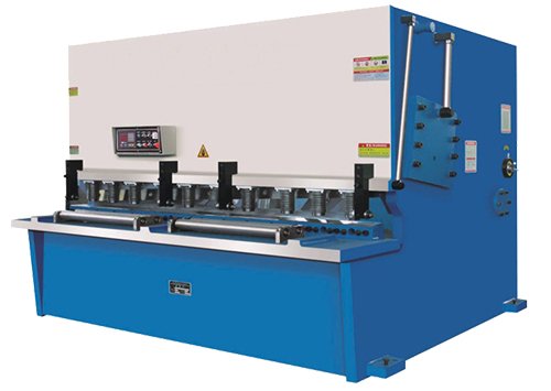
Overview
A hydraulic shearing machine is a type of machine that uses a movable upper blade and a fixed lower blade to apply a shearing force to metal plates of varying thicknesses, resulting in separation of the plates into the desired size using an appropriate blade gap. .
Cutting machines are a type of forging machine that mainly performs metal processing. They are widely used in various industries, such as aviation, light industry, metallurgy, chemical industry, construction, shipbuilding, automobile, electric power, household appliances, decoration and more, to provide specialized machines and complete sets of equipment.
Check out the video below to see it in action.
What is hydraulic cutting machine?
The holding cylinder of a hydraulic cutting machine is driven by the hydraulic system to fix the steel plate, and the left and right cylinders drive the up and down movement of the blade.
The hydraulic cutting machine's holding cylinder operates under the force of the hydraulic system to hold the sheet metal in place, while the left and right oil cylinders control the movement of the blade, moving it up and down.
The upper blade in the blade holder and the lower blade fixed in the blade holders have adequate clearance to apply shear force to metal sheets of various thicknesses and cut them to the desired size.
Hydraulic cutting machine is used for direct cutting of a variety of metal materials to meet the demands of industries such as steel production, shipbuilding, automobile manufacturing, container production, electrical appliances, machinery manufacturing and light industry.
Hydraulic cutting machine working principle
At the beginning of the post, we stated that sheet shearing is carried out by moving the upper and lower blades driven by a hydraulic system.
Different Types of Hydraulic Cutting Machine
Plate cutting machine can be classified into two types: hydraulic shears and mechanical shears.
Hydraulic cutting machines are more commonly used due to their lower power consumption and noise reduction compared to mechanical shears.
In terms of blade holder movement, hydraulic cutting machines can be divided into two categories:
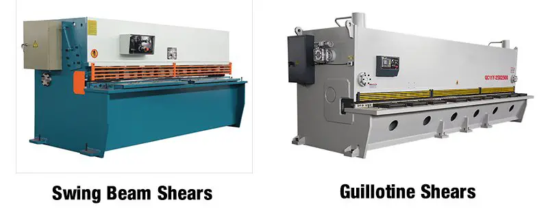
- Hydraulic shears for swing beams
- Hydraulic guillotine shears
Following are various types of cutting machines:
- Guillotine scissors, plate scissors: Uses reciprocating linear movement between two blades to cut metal sheets.
- Manual guillotine scissors, manual plate scissors: Manually operated scissors.
- Hydraulic Guillotine Scissors, Hydraulic Plate Scissors: Scissors operated by a hydraulic system.
- Swivel Blade Shear, Swing Beam Shear: The upper blade holder rotates around a pivot on these shears.
- Hydraulic Swing Blade Shear, Hydraulic Swing Beam Shear: Swing beam shears driven by hydraulic system.
- Multi-Strip Cutter, Coil Cutting Scissors: Uses multi-disc scissors to cut a coil into strips of the desired width.
- Multi-band cutter, sheet cutting scissors: Uses multi-band scissors to cut a metal plate into strips of the desired width.
- Nibbling machine: Processes plates into any desired shape through a step-by-step method.
- Circular Shear, Rotary Shear: Uses a pair of rotating blades to cut plates in a straight or curved line.
- Universal ironworker for punching, bar and section shearing: A machine with dual function of punching and cutting.
- Universal ironworker for shearing plates and sections: A machine with dual function of punching and cutting metal plates.
- Universal ironworker for punch, plate, bar and section shear: A machine with three functions of plate punching, plate cutting and section cutting.
- Universal horseshoe for punching, plate, bar and section shearing, notching: A machine with four functions of plate punching, plate cutting, section cutting and notching.
- Billet shear, section steel shear: Special cutting machines for steel profiles.
- Bar Shear: Special cutting machine for bar materials.
- Alligator Scissors: The top blade of the alligator shears moves in a scissoring motion.
- Reinforcement bar shear: Special cutting machine for reinforcement bars.
- Precision Bar Scissors: Special cutting machine for precise cutting of bars.
- Slab shear: Special cutting machine for slabs.
- Scrap Shearing: Special cutting machine for steel scrap.
- Billet Scissors: Special cutting machine for billets.
Advantages of Hydraulic Cutting Machine
Compared with traditional plate shears, hydraulic plate shears have a significant advantage because they are controlled by a series of codes during operation. These codes are generated using various combinations of characters and depend on the specific requirements of the job.
A major benefit of using code to control hydraulic cutting machine is the ability to precisely control the machine's orientation, speed, and resistance. This is achieved through numerical control, which uses computer programming to operate the machine through numerical combinations.
In terms of positioning, the hydraulic cutting machine has clear advantages. The adjusting rod can rotate continuously around the central axis without dead angles, and the machine operates quietly, providing a quiet working environment that does not affect the mood or health of operators.
The machine is made of durable stainless steel with strong corrosion resistance and stability even in environments with high vibration amplitudes. The operation of the machine is simple and easy to learn, requiring computer skills to operate it.
Furthermore, the machine not only has strong functionality but also has an elegant appearance.
In terms of security, great progress has been made with the hydraulic cutting machine equipped with a robust self-defense fence. In the event of a machine failure, the fence separates the operator from the machine.
Light adjustment also greatly improves speed, allowing quick movement to the correct position for a clearer view of the work situation, adding convenience to the production process and machine operation.
Hydraulic Cutting Machine Parts and Functions
Cutting machine structure
The frame of the cutting machine is constructed of steel plates and includes the left and right plates, work table, clamp support and fuel tank.
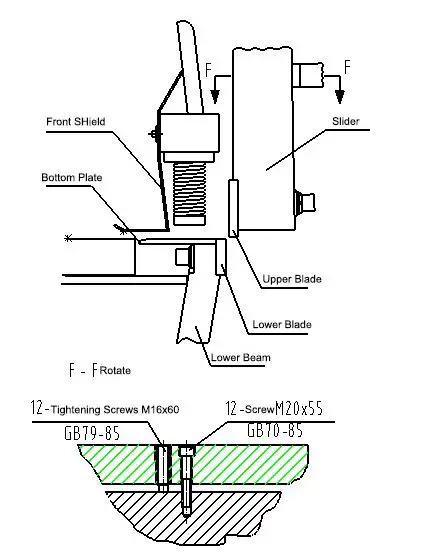
A hydraulic cylinder and sliding block guide bracket are installed on both sides of the rack. This serves as a flexing mechanism to control blade clearance.
The hydraulic holding cylinder on the clamping device can firmly press the plate for cutting.
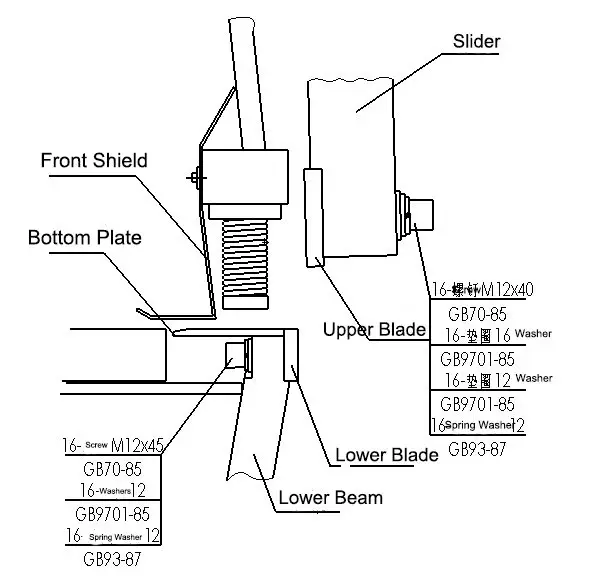
Blade holder
The upper blade is fixed and connected to the hydraulic cylinder, allowing straight up and down movements to transmit shear force and perform cutting.
Furthermore, the backgauge mechanism is fixed on the blade holder to accurately position the size of the cut board.
Shear Blade
The upper and lower shear blades are made of high-grade steel and can be used to shear sheets from low carbon steel to stainless steel. The upper and lower blades have four interchangeable cutting knives to improve blade life.
Backgauge Mechanism
This mechanism, which is fixed to the blade holder, includes a backgauge adjusting motor, microdynamic adjustment mechanism, backgauge lifting mechanism, digital display device, transmission screw and guide bar.
The movement of the back stop on the cutting machine is driven by the engine and causes the back stop stop plate to work, thus allowing cutting to the right length.
Fuel tank
The fuel tank is installed at the base of the oil tank behind the cutting machine. The left side of the tank houses the integrated hydraulic valve block, hydraulic oil pump and main engine.
An oil gauge is located on the left side of the tank and hydraulic oil should be added to the intermediate level indicated by the gauge.
Slack adjustment device
The shear force can be optimized by adjusting the gap between the upper and lower blades and the plate thickness. This helps to extend the life of the blade and ensure product quality.
Adjustment rule: The gap should generally be adjusted to 10% of the thickness of the cut material.
Front Supporter
A side holding device is fixed to the work table to ensure that the cut board is perpendicular on both sides.
Finger protection plate
The finger protection plate of the cutting machine is installed on the clamp bracket of the machine and is designed to control the safe finger distance.
To ensure a safe finger distance, the position of the finger protection plate must meet mechanical safety standards.
Safe distance for finger protection
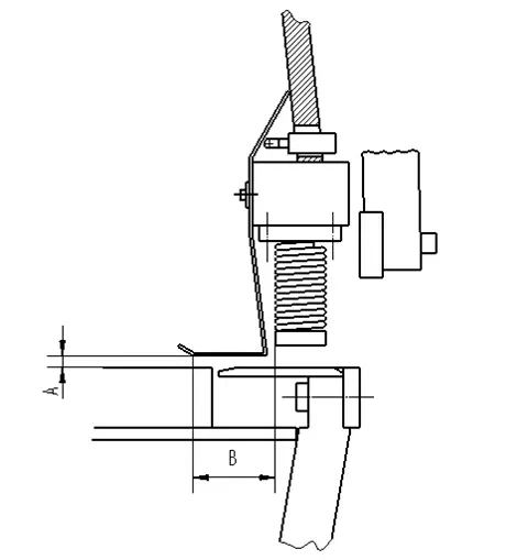
| Garden shears | max.A | min.B |
|---|---|---|
| 8/6.5/3000 | 12 | 80 |
| 06/08/4000 | 12 | 80 |
| 10/3000/4000 | 20 | 120 |
| 13/3000 | 23 | 200 |
Note: These dimensions comply with mechanical safety standards.
It is important to avoid placing your fingers between the plate and the cutting machine table when positioning the plate in the anti-return block. This can cause the plate to press against your fingers during the pressing process.
Furthermore, when the thrust block is not in position, the plate should not be pushed through the finger protection plate to avoid possible finger injuries.
Press and hold the cylinder
To prevent the plate from moving during the cutting process, the holding cylinder is used to firmly press the plate.
Shearing Machine Electrical System
The main purpose of the electrical system is to start the oil pump motor, drive the oil pump to supply power to the hydraulic shear and control the power supply.
The control circuit mainly connects the solenoid valve and oil pressure, based on the operating instructions, to drive the up and down movement of the blade holder and ultimately achieve the cutting purpose.
In addition, electricity is used to control blade travel, back-and-forth movement, cutting line alignment, gap adjustment, and cutting angle.
Shear Machine Hydraulic System
The hydraulic system is composed of the main oil pump, hydraulic components, hydraulic cylinder, pressure cylinder, hydraulic pipes and so on.
The hydraulic oil pump provides shear pressure to hydraulic equipment. The hydraulic system controls system pressure and the direction of hydraulic oil flow.
The hydraulic cylinder drives the movement of the blade holder to cut the sheet. The holding cylinder mainly presses the workpiece to ensure precision during the cutting process.
Hydraulic Cutting Machine Specifications
1. Shear thickness
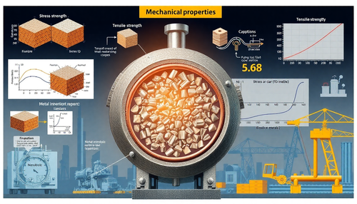
The maximum thickness that can be cut by a hydraulic cutting machine is limited mainly by the strength of the cutting mechanism and ultimately depends on the shear force.
There are several factors that affect the shear force, such as edge clearance, edge sharpness, shear angle (for flat knife cutting), shear speed, shear temperature, width of the sheared surface, and most importantly, the strength of the material being cut. .
Currently, the typical shear thickness for hydraulic shear machines is less than 32 mm, as greater thicknesses are not economical or efficient from a utilization perspective.
2. Shear sheet width
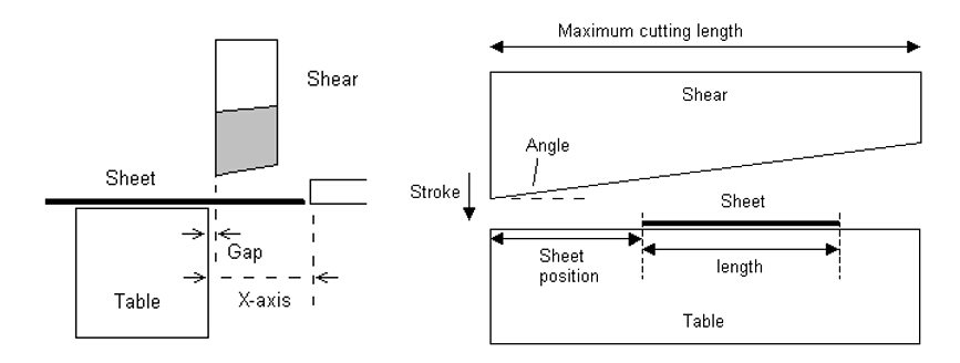
The cut sheet width refers to the maximum size of metal that can be cut at one time in the shearing mechanism's scissor direction.
This measurement is based on the width of the steel plate and the manufacturer's requirements (the width of the shear plate is typically less than the length of the cutting edge).
This cutting method is known as transverse cutting and longitudinal cutting is a type of multiple contact shearing.
As long as the width of the strip is less than the depth of the cutting mechanism throat, the size is not limited.
With advances in technology, the sheet cutting width is increasing, and hydraulic cutting machines with sheet cutting widths of up to 6,000 mm are becoming more common, with some foreign sheet cutting machines reaching a maximum sheet width 10,000 mm.
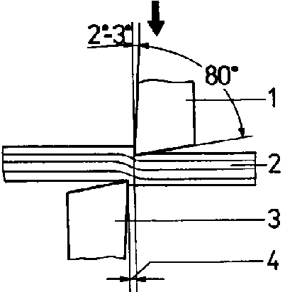
3. Shear angle
In order to reduce bending and distortion in the sheared metal sheet, a smaller shear angle is generally used, which can increase the shear force but also improve the shear quality.
This increase in shear force can also have an impact on the strength and stiffness of the stressed parts of the shear.
4. Deep Throat
The longitudinal cutting method requires certain throat depth specifications for the cutting mechanism.
Currently, the trend is to have a shallower throat depth, which improves chassis rigidity but reduces the overall quality of the machine.
Hydraulic Cutting Machine Applications
Hydraulic cutting machines are widely used in a variety of industries, including decoration, home appliances, electric power, automobiles, ships and aerospace.
In the decoration industry, hydraulic guillotines are often used in conjunction with bending machines to produce stainless steel doors and windows and to decorate special places.
In the power and electrical industries, the hydraulic cutter is used to cut plates into desired sizes and then process them through a press brake, such as in the production of electrical cabinets, refrigerators and air conditioning housings.
Large hydraulic cutting machines are commonly used in the automobile and shipbuilding industries for sheet metal cutting work followed by secondary processing such as welding and bending.
High precision is often required in the aerospace industry, therefore, CNC hydraulic cutting machines and electro-hydraulic synchronous CNC bending machines are often selected for their precision and efficiency.
Hydraulic cutting and bending machines also play important roles in several other industries.
How to use hydraulic cutting machine
Pre-operation preparation
- Wipe the oil off the surface of each cutting machine component, ensuring the ball valve is in the open position.
- Lubricate the lubricating parts.
- Fill the tank with thickened hydraulic oil N32-N46 (the oil must be filtered).
- Ensure proper grounding of the machine and turn on the power supply. Check the coordination of each electrical component.
- Before starting, especially if the accumulator needs to be re-inflated, check the position of the ball head.
Steps to use hydraulic cutting machine:
- Turn on the machine and operate it for a certain number of cycles to ensure that plates of different thicknesses can be cut under normal conditions (from thin to thick) for testing purposes.
- Open the pressure gauge during cutting and observe the oil pressure value. If there is an abnormality, adjust the overflow valve to meet the requirements.
- Adjust the blade gap to a suitable position based on the board thickness.
- Transfer the board to the work table.
- Adjust the backgauge to the proper position based on the cut sheet size.
- Push the plate so that it contacts the backgauge plate and set the cut size.
- Step on the pedal to cut the steel plate.
- Repeat steps 4 through 6 to cut the next sheet.
- After cutting a piece of steel, replace it and repeat the processing from steps 4 to 8.
- Turn off the power when work is completed and maintain the equipment daily as specified in the cutting machine's daily maintenance instructions.
Safe Operating Guidelines for Hydraulic Cutting Machine:
- The operator must be familiar with the general structure and operation of the cutting equipment.
- The operator must be trained in the use and maintenance of cutting equipment.
- Lubricate the cutting machine according to the lubrication instructions, check the oil level and quality, and cover the oil cup.
- Before operation, align the cutting blade. Blade clearance should be set based on the thickness of the material being cut, typically 5-7% of the material thickness. Adjust the gap by turning the handwheel by hand to make the upper and lower blade alternate once, then check the gap with a feeler gauge.
- Based on the requirements of the material to be cut, loosen the anchor bolt, adjust the position of the retaining plate and tighten it. The cutting machine should be operated 2 to 3 times before starting work to ensure good lubrication and error-free operation.
- Do not use percussion to loosen the thrust device or adjust the blade clearance. When adjusting the guide rail clearance and blade clearance, the machine must be stopped before making any adjustments. Do not reach into the cutting area or handle material during operation.
- The blade must be sharp and must be sharpened or replaced immediately if it is damaged or worn.
- When cutting different thicknesses and types of material, properly adjust the clamp spring pressure and blade clearance to avoid spring breakage or damage to the blade edge.
- Do not cut steel bars using the hydraulic cutting machine. Do not place any other items on the work table to avoid damaging the blade.
- The operator must not leave the machine during operation or allow another person to operate it.
- Pay close attention to the clamping mechanism, clutch and brake to detect any signs of abnormal failure. Stay alert while clipping and if you detect any abnormal behavior in the machine, stop clipping immediately, turn off the power and inform maintenance personnel.
- Before leaving work, turn off the power, clean the equipment, and keep a record of the inspection.
- Do not cut excessively long or thick sheets, high-speed steel, tool steel or cast iron.
- The clutch must be off before starting and the engine must not start under load.
- Before you begin, test the empty cut. When everything is working well, start the cutting operation.
- Do not cut explosive items, rods, excessively thin materials, or non-metallic materials.
- Check the pull rod for signs of failure and make sure the set screw is secure. Keep fingers out of the way of the blade when feeding material. Do not cut material with two operators at the same time and do not stand behind the cutting machine.
Matters to be considered when operating the hydraulic cutting machine
(1) Regularly check the blade clearance and adjust it according to the thickness of the different materials being cut;
(2) Make sure the blade is sharp and the cutting surface is free from scars, gas cuts and protruding burrs;
(3) When making adjustments to the machine, it must be turned off to avoid injury and damage to the machine;
(4) If abnormal noise or overheating of the oil tank is detected during operation, stop the cutting machine immediately to investigate the problem. The highest temperature of the oil tank must not exceed 60°C;
(5) Do not attempt to cut strips as this may damage the machine. The minimum width of the material to be cut must not be less than 40mm;
(6) Please note that the cutting capacity of the hydraulic guillotine depends on the strength of the material to be cut. For example, with a maximum cut thickness of 16mm for Q235 steel (with a tensile strength of 450Mpa), the cut thickness for Q345 steel would be 13mm. For Q235 steel with a cutting thickness of 8mm, the cutting thickness for Q345 steel would be 6mm.
Hydraulic Cutting Machine Blade
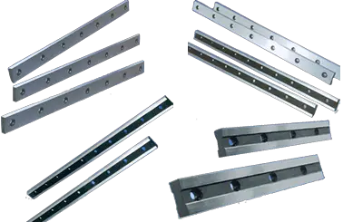
Cutting machine blade material
Standard blade hardness
| 6.5/10mm | CDH | 58/59 |
|---|---|---|
| 13/16mm | CDH | 56/57 |
These blades are capable of cutting standard cold-rolled sheets and most stainless steel sheets.
When cutting large quantities of stainless steel or hard materials, sharp edges may occur during the cutting process.
In these cases, an optional blade with hardness HRC 56/57 for 6.5/10 mm scissors is available as a solution.
You can also check the detailed 8 commonly used materials of hydraulic scissor blade
Cutting machine blade angle adjustment
The blade angle and clearance calculation depend on the standard material.
The gas cabinet has a diagram that can be adjusted at any time to obtain better cutting results.
For example, increasing the “tilt angle” can reduce the cutting edge, but it can also cause deformation when cutting strips. On the other hand, decreasing the “tilt angle” can reduce deformation, but can also result in burrs.
Minimum cutting width of hydraulic cutting machine
The width of the shear strip should not be less than three times the thickness of the plate when precise shearing is not required.
For precision cutting, the width of the cut material must be at least 6 times the thickness of the board to avoid distortion or bending. The wider the sheared material, the smaller the deformation.
Hydraulic Cutting Machine Cutting Accuracy
When evaluating the shear quality, the following data should be taken into account for an ordinary 2 mm cold-rolled sheet:
- When setting
- When setting
- The repeat accuracy of X-axis positioning should be 0.02 mm.
Observation:
- The length of the sample can be equal to the width of the plate being sheared.
- The tensile strength of the sample should not exceed σb≤450 Mpa.
Cutting Machine Blade Assembly
Instructions for installing the upper and lower blades of a hydraulic cutting machine:
Top Blade Installation:
- Assemble the blade and firmly tighten the M1240 screw on it.
- Do not tighten the screws at both ends yet.
- Use a stick to hold the blade in place, then tighten the installed M1240 screw one by one until the blade surface is fully in contact with the slider.
- Lower the slider, turn off the pump motor, and tighten the M12*40 screws at both ends of the blade.
- The blade screw tightening torque must be 35 N/m.
Lower blade installation:
- Turn on the oil pump and raise the slider to the highest point.
- After the oil pump is turned off, place the blade and loosen the M1245 hex screw (do not tighten too much for now).
- Use a stick to press the blade so that it is close to the bottom of the work table.
- Tighten the M1245 screw as necessary.
Note: Blade screws must be tightened to the specified torque to ensure proper machine operation.
Blade gap adjustment
Blade clearance directly affects the quality of the cut surface and the service life of the blade.
1. Blade clearance too small
Typically, the standard gap between the upper and lower blade is 0.02 mm, which is equivalent to the thickness of a standard A4 paper.
A commonly used method to adjust the blade clearance during installation is to use the cutting machine to cut paper.
If the blade gap has been adjusted too small:
The tip of the blade is under excessive pressure, which can directly damage the tip and blunt it.
Displacement may occur between the upper and lower blade, resulting in the upper blade cutting into the lower blade. This can cause the blade's cutting edge to crack, which poses a risk to the operator.
2. Blade clearance too large
This is a common mistake made by non-professionals during blade installation. To prevent the blades from clashing, they often increase the distance unnecessarily. This is incorrect.
When the blade clearance is too large, the accuracy of the cutting plate will be affected and there will be a lot of metal burrs on the cutting edge, especially when cutting thin sheet materials.
The metal sheet will also get stuck between the top and bottom blades, making it difficult to remove. This not only wears down the blades, but can also cause the cutting machine to shut down. However, this problem may not be as noticeable when cutting thick sheet metal.
Regular adjustment of the blade clearance is necessary after prolonged use of the scissors. We recommend setting the blade gap to about 10% of the sheet metal thickness.
The lower blade is fixed on the hydraulic cutting machine, and the blade gap can only be adjusted by changing the position of the upper blade. The minimum clearance should be between 0.05-0.1 mm.
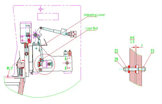
The blade gap at the ends can be adjusted by adjusting the pole (as shown in the figure).
If the gap between the lower blade does not meet the requirements, it can be adjusted by referring to the figure and adjusting the M16 60 and M12 65 hex screws to ensure that the parallelism margin of the upper and lower blade is within 0.05mm.
It may be necessary to repeat adjustments of the M1265 and M1660 internal hex screws to obtain optimal blade clearance.
Hydraulic Cutting Machine Maintenance
Daily scissor maintenance involves daily lubrication, cleaning the tank, and cleaning the cutting machine.
1. Safety Instructions
When carrying out any maintenance on the cutting machine, it is important to first disconnect the power supply.
Wait 20 seconds for the capacitor and servo amplifier to completely discharge.
During operation of hydraulic parts, the slider may move, so it is important to follow these guidelines:
- Do not place arms or feet between the upper and lower blades;
- Before removing the valve:
- Turn off the pump
- Lower the slider to the oil cylinder without oil
- If it is not possible to lower the slider, use a block of wood to cushion it and pay attention to any pressure changes in the system due to the removal of the slider valve. Please note that no operations should be carried out on the cutting machine without adequate safety measures.
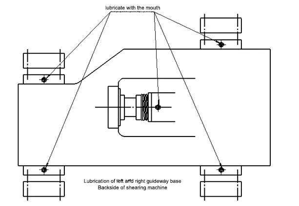
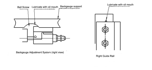
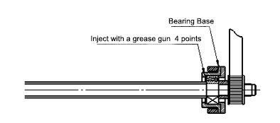
2. Cutting machine lubrication
The cutting machine must be lubricated once a week (or every 40 hours). Use a calcium-based grease and inject it into each lubrication point with a grease gun.
The lubrication points are shown below:
| No. | Lubrication point | Grease |
|---|---|---|
| 1 | Ball screw, nut and screw end bearing | Calcium-based grease |
| two | Guide rail and sliding guide base | Calcium-based grease |
| 3 | Sliding Block Guide Rail | Calcium-based grease |
| 4 | Guide rail and clearance adjustment screw and nut | Calcium-based grease |
3. Hydraulic oil and calcium grease
Scissors are recommended to use the following hydraulic oil:
| Manufacturer | Hydraulic oil |
|---|---|
| ESSO | NUTO H46 |
| SHELL | TELUS 46 |
| GULF | HARMONY 46 AW |
| SHOVEL | HLP46 |
| TBXACO | RANDO OIL 46 |
| MOBILE OIL | MOBILE DTE 25 |
4. Change the hydraulic oil
Hydraulic oil should be replaced after the first 2,000 hours of operation and then replaced every two years or after 4,000 hours of use.
- Before removing the tank cap and accessing the piping, it is important to clean the area to avoid contamination.
- Hydraulic oil should be drained when it is hot and the slider is at top dead center.
- Clean the inside of the tank with a clean cloth and a suitable solvent.
- Replace oil filters and add new hydraulic oil.
- Before restarting the cutting machine, run the oil pump for about an hour to circulate the new hydraulic oil.
5. Hydraulic cutting machine maintenance procedures
To ensure reliable operation of the cutting machine, it is important to follow the following procedures, which are illustrated graphically.
Please note that the specified time listed below is based on a 5-day work week, with 8 hours of work per day.
| Item | Points of attention | Period |
|---|---|---|
| Whole body | Brush off dust and dirt from the machine, gently lubricate the blade | weekly |
| Slider | Gun lubrication | weekly |
| Backgauge support bearing | Gun lubrication | weekly |
| Backgauge ball screw | Gun lubrication | weekly |
| Slide guide rail | Check tower adjustment | 3 months |
| Check backgauge positioning | If the position error of the backstop blocks exceeds +0.1mm, restart | 3 months |
| Hydraulic parts and systems | Check the oil level in the tank. If you need to change the new oil, change the filter to 20um | weekly |
| Drain the old oil and add new oil | 12 months for the 1st time | |
| Check all valves, hydraulics, piping and connectors to prevent leaks, blockages and replace when necessary. | 3 months | |
| Check the cleanliness of the import and export filters | 3 months | |
| Pedal | Check the pedal pedal in case of deformation, breakage, etc. | a month |
| Electrical Control Equipment | Check the limit switches on the electrical panel, and wear and burn should be replaced in time | 3 months |
| Garden shears | Observe the wear and abnormality of pneumatic shears | 3 months |
| finger protector | Check the sheet metal shear protection device to prevent your finger from entering the dangerous area | a month |
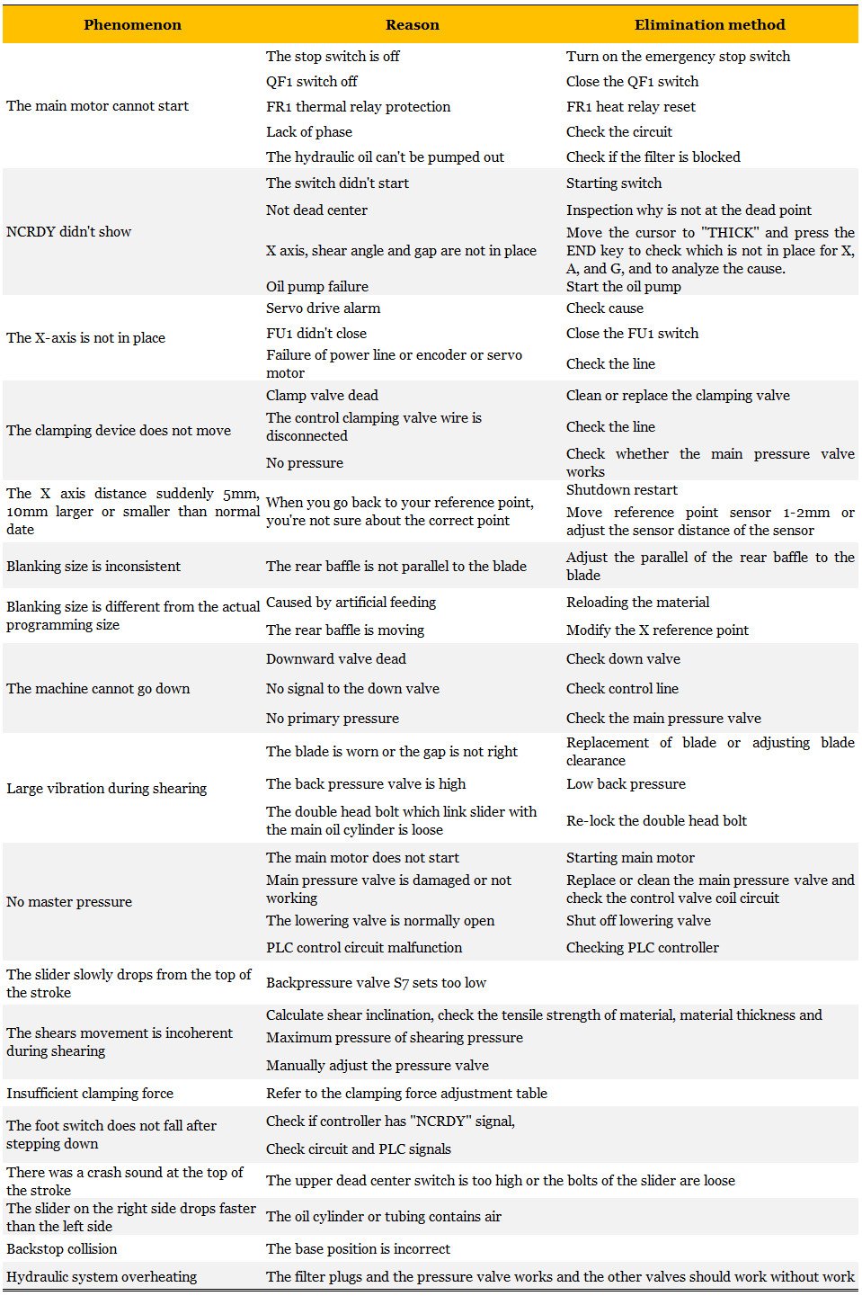
Hydraulic Cutting Machine Troubleshooting
Hydraulic Cutting Machine Instruction Manual
You can click the link below to view the instruction manual for swing beam shears as well as guillotine shears.
- Hydraulic Swing Beam Cutting Machine Operation Manual
- Hydraulic Guillotine Operation Manual
Hydraulic cutting machine drawing
** Circuit diagram of hydraulic shear
Here are the drawings:
Electric diagram
** Hydraulic schematic diagram
Here are the drawings:
Hydraulic Diagram
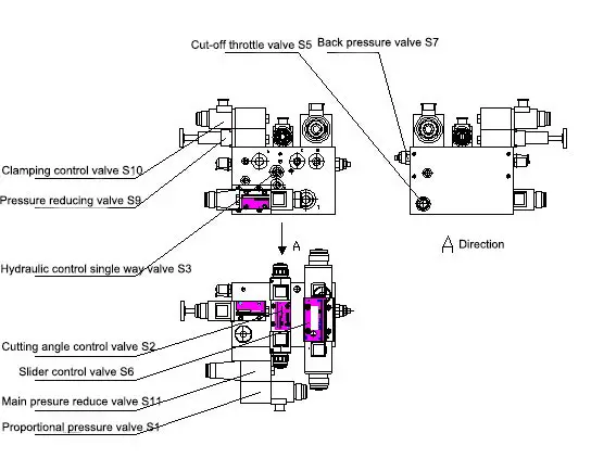
1. Slider movement up and down
When oil from the main oil line is directed to the three-position, four-way directional control valve S6, S6Y1A is energized. Oil then enters S6B through S6P, opens one-way valve S8 and flows into the lower chamber of the right cylinder (the left and right cylinders are connected in series), causing oil to flow from the right tank to the lower chamber of the left cylinder.
Oil in the upper chamber of the left cylinder enters S6A and then S6T, causing the slider to move upward.
If S6Y1 is energized, oil will enter S6A through S6, then the upper chamber of the left cylinder, and then the upper chamber of the right cylinder.
The oil will overcome the pressure from the back pressure valve S7 and enter S6T through S6B, then return to the oil tank, causing the slider to move downwards.
2. Adjusting the shear angle
If there is no set value for the shear angle of the cutting machine, the slide block cannot move up and down. Therefore, the shear angle must be set via the controller.
The shear angle adjustment is as follows:
When the oil is directed to the three-position four-way directional control valve S2 and Y2A is energized, the oil will enter S2B through S2P, open the hydraulic control one-way valve S3 and flow into the lower chamber of the left cylinder and the upper chamber of the right cylinder, causing the upper chamber of the left oil cylinder not to form a circuit and not to move.
When the oil in the lower chamber of the right cylinder returns to the oil tank through S6T, the backpressure valve S7 and the valve S6B, the shear angle becomes smaller.
On the other hand, if Y2B is energized, oil will enter S2A through S2P, open one-way valve S4 and flow into the lower chamber of the right oil cylinder.
The oil in the upper chamber of the right cylinder can only enter the hydraulic control one-way valve S3 (at this point, the S3 valve is open), and the oil will enter S2T through S2B, causing the shear angle to become larger.
The relationship between shear angle and shear force:
| mild steel (mm) |
6 | 8 | 10 | 13 | 13 | 13 | 13 | 16 | 16 | 20 |
|---|---|---|---|---|---|---|---|---|---|---|
| Stainless steel (mm) |
3 | 4 | 6 | 8 | 8 | 8 | 8 | 10 | 10 | 12 |
| Shear force (KN) |
132 | 220 | 430 | 730 | 620 | 620 | 650 | 730 | 850 | 1270 |
| Adjusting the shear angle (°) |
0.5-2.5 | 0.5-2.5 | 0.5-2 | 0.5-2 | 0.5-2.5 | 0.5-2.5 | 0.5-2 | 0.5-3 | 0.5-2.5 | 0.5-3 |
3. The work of the retaining cylinder
When oil enters directional control valve S9 through clamping proportional control valve S10 (whose proportional pressure is controlled by an electric arc pressure adjustment switch), after activation of S9, oil will enter S9A through S9P will then enter the upper chamber of the clamping device, causing the clamping piston to move downward and create compression.
When the S9 loses electricity, the clamping piston will be pushed up by the clamp's internal spring, forcing oil in the upper chamber of the clamping cylinder into the S9T through the S9 valve, resetting the clamping device.
** Structure drawing of hydraulic cutting machine

Hydraulic Cutting Machine Vulnerable Parts List
| No. | Item | Amount | Price (RMB) |
|---|---|---|---|
| 1 | toothed belt | 1 | 150 |
| two | O-Ring | 1 | 10 |
| 3 | O-Ring | 1 | 12 |
| 4 | Sealing ring | 4 | 174 |
| 5 | Dustproof Ring | two | 302 |
Responsibility of the hydraulic cutting machine operator
Under the guidance of the sheet metal workshop director, we must learn to comply with company regulations, follow leadership directives, maintain personnel unity, make positive efforts, act in a cost-effective manner, perform quality work, and produce qualified products .
- Responsible for daily routine maintenance by checking, repairing, adjusting and tightening shears and keeping records
- Familiar with occupational safety technical operation procedures and strictly follow safety technology and operating procedures
- Master the normal operation method of the cutting machine, can accurately assess abnormal situations, and take emergency measures timely and correctly
- Operate strictly in accordance with the operation rules, the equipment can only be started when the working environment is normal
- Check the sufficiency of the oil storage tank, check the valves and pipelines after starting the oil pump, and ensure that the pressure meets the requirements
- Observe the resistance of the blade movement and start cutting when the test is normal (sudden start is prohibited)
- Do not cut laminated sheets, cut edges of boards with burrs, or cut narrow boards and short materials that cannot be pressed firmly
- Adjust the blade gap according to the plate thickness (do not exceed 1/30 of the plate thickness)
- The blade must be firmly fixed and kept parallel to avoid accidents
- Keep blade edge sharp and repair/replace if dull or cracked
- Press materials firmly onto the board while cutting and do not cut under pressure
- Do not adjust the hydraulic valve yourself
- Do not use cutting machine for super length/thickness, or for cutting steel, high carbon steel, alloy tool steel, cast iron or brittle materials
- Check frequently whether the fixing screws are loose
- Do not operate the cutting machine alone, coordinate with another person the delivery of material, accuracy of dimensions and collection of material
- Adjust the blade gap according to the board thickness and do not cut two different specifications/materials
- Keep the operator's fingers 200 mm away from the scissors and leave the compression device
- Determine the cut thickness according to the plate limit strength/thickness curve diagram
- Do not place other items on the counter
- Clean after stopping the cutting machine
- Run the cutting machine empty after adjusting the blade (alignment) for testing
- Stack the finished product, clear the field, turn off the power and lock the distribution box before leaving work
Hydraulic Cutting Machine Price
Commonly used hydraulic shearing machines are mainly designed for cutting steel plates with a thickness of 4-8mm and a width of 2.5-3.2m.
Normally, a 4*2500 hydraulic swing beam shear costs about 6000 dollars, while a 6*3200 hydraulic swing beam shear costs about 10000 dollars.
It should also be noted that the price of a hydraulic guillotine is approximately 2,000 dollars more than that of a swing beam shear.
The difference between swing beam shear and guillotine shear can be seen here.
How to choose the right hydraulic cutting machine
- Determining Hydraulic Cutting Machine Specifications and Cost Range: When purchasing a hydraulic cutting machine, it is important to consider the specific needs and product parameters to determine the correct specifications and cost range.
- Finding a Manufacturer: The first step in the process of finding a manufacturer is to determine if they have the necessary machines. This may seem simple, but it's important not to skip this step. A useful resource for finding hydraulic cutting machine factories around the world, including hydraulic cutting machine companies in China, can be found in this post.
- Checking models: Different manufacturers often supply various machine models and may even order from other companies, so it is important to carefully check whether the model you need is available.
- Examining the company and machine: When visiting the company to see the machines, it is important to gather as much information as possible about the machine and after-sales service. Make an informed decision by considering several factors and choosing a manufacturer with a good price and excellent service.
- Signing a contract and making a deposit: After determining the manufacturer, the next step is to sign a contract and pay a deposit. It is important to carefully review the terms of the contract and ensure that they are fair and do not violate any laws.