What is the use of a grooving machine in sheet metal work?
A groover, also known as a V-groove or V-grooving machine, is a tool used to scribe and groove V-shaped grooves in metal plates. This can reduce the bending radius and improve the appearance of sheet metal parts.
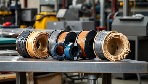
The machine is particularly useful in industries that require high-precision sheet metal processing, such as elevator manufacturing, packaging materials, stainless steel processing, household appliance production and display stands.

(5) The width and thickness of the plate are set as working parameters.
(6) Press the Start button to begin grooving when the position light flashes. When the depth light flashes, press the “Move” button to move to the next channel position.
(7) Press “manual operation” to manually control the operation screen.
(8) Press the “open channel preparation” button to move the beam to the front of the platform and initialize the various channel parameters to prepare the channel of the next metal plate.
The beam will not move if the beam position is less than the initial position offset, but the parameter initialization is normal and the button should not be pressed during the channel.
(9) To replace the blade, a channel pause button is pressed.
When the button is pressed, the channel machine will stop working, and then press the button to restart the machine.
(10) Press “parameter setting” to jump to the parameter setting screen.
Manual operation
(1) “Beam forward” means moving the beam forward manually, and the moving speed is set in the system parameters.
(2) “Beam backward” means moving the beam backward manually, and the moving speed is set in the system parameters.
(3) “Tool holder left” means moving the tool holder to the left manually, and the movement speed is set in the system parameters.
(4) “Tool holder to the right” means moving the tool holder to the right manually, and the movement speed is set in the system parameters.
(5) “Tool holder up” means moving the tool holder upward manually.
(6) “Tool holder down” means moving the tool holder down manually.
(7) “Operating Instructions”: Press this button to move the screen to the operating instructions screen.
(8) “Original alignment”: press this button to perform the function of returning the original to correct the beam position.
In general, there is no need to perform the return-to-origin function (because the computer does not have the location memory function).
However, if the channel machine has stopped for more than two days, or if the position is not correct due to some other circumstances, the return to origin function must be performed first after electrification to ensure the normal operation of the machine.
Parameter Setting
- Press the “parameter setting” button to access the parameter setting screen, where channel spacing can be set for up to 50 channels.
- The first groove can be defined with a minimum value of 8mm and a maximum spacing of 1220mm, with no limits for the other grooves.
- After pressing the menu for the parameter you want to configure, a digital keyboard will appear on the screen. “ENT” is the entry confirmation button, “ES” means the entry is canceled and “CR” is the entry reset button. All parameters are positive and if a negative number is entered, the machine will report an error.
- Press the “return” button to return to the configuration screen.
- In parameter setting, press the “system parameters” button to return to the system parameters screen.
- After setting the parameters, check them carefully according to the process sheet to avoid errors.
- Distance #1 refers to the vertical distance from the 1st groove to the starting point. Distance #2 refers to the vertical distance from the 1st slot to the 2nd slot, and so on, for each of the slot distances.
- On the parameter setting screen, the current process can be cleared by selecting “parameter full clear”.
System parameters
System parameters have several types of buttons:
(1). “Deceleration advance” is the position where the beam decelerates from high speed to a constant speed.
This parameter is crucial for positioning.
If each positioning exceeds travel, increase this parameter, generally set to 8mm, with a maximum adjustment of 9.999mm.
(two). “Forward positioning” is the designated pre-stop positioning position.
After stopping, the beam moves to the positioning position under the action of inertia.
If the channel machine does not stop at the correct position for each stop, it means that the parameter setting is too large.
Otherwise, the parameter setting will be too small. The maximum data of this parameter can be set to 0.8 mm.
(3). “Allowable error” is the permissible error after positioning. Grooving is not permitted if not in this range and manual correction is required.
(4). “Starting point error” refers to the distance between the tip of the blade and the edge after origin correction.
The minimum setting is 8mm.
Otherwise, the front positioning proximity switch needs to be adjusted in time.
Groove (V-cut)
1). Grooves must meet the following conditions
- The emergency stop switch has not been pressed;
- Positioning (indicator light flashing);
- The side presser pressed the plate;
- There is no limit to the right or left of the tool holder;
- The beam is not outside the travel range;
- The tool holder stop button is not pressed;
- The longitudinal position of the blade tip ≥ 8mm;
two). Moving beam
When finishing the channel, press “Move Beam” button to move the beam to the next channel position, which is automatically added to the target position by the channel machine.
After the beam automatically positions itself, a channeling process must be carried out before the beam can move again. This process continues until all channel lines have been completed.
3). Conditions for moving beams
- Beam travel no more than 1220 mm;
- Position positioning does not flash OK;
- The beam position is not greater than the target position;
- Monitoring pressure lifting device;
- The emergency stop switch is not pressed;
- The beam front limit switch is connected;
- Slotted motor contactor is not pulled.
4). Press the “Grooving ready” button to move the beam to the front of the platform.
Channel machine accessories
- Inverter
- Programmable Controller
- stepper motor
- stepper driver
- Encoder
- Proximity sensor
- Exchange energy
- Touch screen
The operation method for mechanical channel
- Place the metal sheet on the countertop. If the metal sheet has a protective film, the side with the protective film faces down. One side of the sheet metal adheres to the reference block in front of the work table.
- Press the sheet metal pressure button to pinch the edge of the sheet material and complete positioning of the sheet material.
- Adjust the position of the proximity switch limit block on the left and right sides of the tool holder sliding block appropriately according to the length of the plate.
- Determine the spacing of the slots and the fore-and-aft adjustment of the beam. Adjust “origin alignment” on the PLC touch screen to achieve accurate positioning. That is, the beam shift to the first slot position, press the follow-up pressure button to firmly press the plate material.
- The 35mm thick blade block is used to set the starting point of the blade, lock the pressure screw, and check the blade block to ensure the blade height. This is important preparatory work to ensure accurate groove depth and the production of secure grooves.
- Check that the blade is in good condition and if it is very worn, loosen the blade. Press the screw and rotate the blade 90 degrees, that is, replace it with a new blade. Or turn the blade over and change another blade surface.
- Press the work-in button on the electrical box operation panel to perform the first channel. Generally, the first channel depth is 0.3mm, followed by the thickness of the processed plate.
- After the groove depth meets the requirement, let the grooving blade exit the surface of the board. The sliding frame automatically moves to the preset right limit position. The PLC controls the movement of the beam to the next groove and then the second groove is processed. Until the entire machining process is completed, press the follow-up material pressing “release button” on the mobile operating station and loosen the follow-up pressing device. The PLC executes the next slot positioning instruction. The beam immediately returns to the next slot and repeats until all slots are completed.
- After the completion of the channel work, loosen all pressing devices, place the beam in the appropriate position, remove the plate materials, and clean the work table.
- When spray cooling is required, the switch on the electrical cabinet will be opened first and the cooling system will be automatically lubricated during the cutting process.
Safe Operation Procedure for V-Channel CNC Machine
- The CNC grooving machine must be maintained and operated by a specially designated person;
- The CNC V grooving machine operator must undergo professional department training. After passing the exam and obtaining the qualification certificate, the operator can operate independently;
- Before operation, wear long-sleeved work clothes (to avoid burns from splashes of fluted debris), and gloves should be worn when loading and unloading the plate;
- Before starting the V-channel machine, check whether the machine table is clean, especially between the clamps and the table;
- Reset the origin after starting. When working, check whether the part complies with the process requirements and correctly enter the channel size and depth;
- When the operator is placed on the small sheet, remember to handle it lightly. Before loading, clean the surface of the machine and the feeding table, leaving no residue of slotted wire and other sundries;
- When operating the grooving machine, check whether the plate is pushing towards the origin. Personnel must not extend their heads and any part of their body into the engine area of the machine (to avoid injury caused by the machine). The air gun and hand must not be placed under the fixed clamp;
- When the grooving machine is in motion, operation must be stopped if the machine or materials collide. First, reset the origin to avoid the movement of the origin at the time of collision;
- After grooving, carefully place the sheet in the designated position to prevent the part from being scratched;
- After operation, carry out daily maintenance of the milling machine, turn off the power and clean the workplace.
Gantry (horizontal) vs. gantry V grooving machine Vertical V-grooving machine: Which one to choose?
When deciding to buy a V-channel machine, you may face the dilemma of choosing between a gantry type (horizontal) V-channel machine and a vertical V-channel machine. Let me explain the difference between the two.
Currently, there are two types of V-groove machines on the market: vertical and horizontal.
The structure of the vertical V groover is similar to that of the door frame type. The fixture is used to position the board in the corresponding processing position. After clamping, the V-groove is processed by the movement of the milling cutter. The tool only performs the linear movement of processing, and the plate is moved to cooperate with the tool processing.
The principle of the horizontal V groover is opposite to that of the vertical V groover. It has a large work table, and the board is fixed to the table using pressure clamps. The cutter is a gantry automatic mechanical structure. The tool moving device on the gantry first locates the machining route on the Y axis, and then the gantry drives the tool to carry out V-groove machining on the X axis. The plate is clamped and processed by the movement of the cutter.
Each type of groover has advantages and disadvantages (Table 1).
Table 1 Comparison of vertical and horizontal V-groove technology
| Item | Vertical V groover | V gantry groover |
|---|---|---|
| Processing range | When processing parts that need to be grooved, if the part is long, it is necessary to add a table to transport the part when processing the short side, which is inconvenient to operate. | Three-axis CNC machining with a wide processing range, suitable for a variety of large formats. |
| Desktop Processing Technology | The surface of the work table is made of high-quality molded steel after general heat treatment and is finely ground by a grinder. The fineness of the surface achieves a mirror-like effect. | The surface of the work table is welded by ordinary iron plates. The hardness of the piece is greater than it. Grooved steel wire, damaged blades, etc. will cause corrosion on the surface of the work table (requires the self-flattening function to restore the surface of the work table regularly). |
| Processing efficiency | The minimum distance between the V-shaped groove and the edge is 10 mm and the cutting speed is 40 m/min. | The minimum distance between the V-shaped groove and the edge is 8 mm, and the cutting speed is 50 m/min or higher. There is no need for alternative feeding, so it is more efficient. |
| Energy loss | The tool holder moves back and forth with less losses (main motor power 4.4 kW). | The gantry and tool holder move back and forth together, and the loss is large (the power of the main motor is 5.5 kW). |
| Security | The vertical grooving machine automatically clamps the workpiece by hydraulic pressure, automatically positions and works. The operator is away from the moving parts of the machine. | The workpiece is clamped within the machine's range of motion. The gantry moves at high speed and the control part works with the gantry. The operator needs to pay attention to safe use. |
| General effect | Due to the need for automatic feeding after fixing the part, the iron scraps generated by the groove often scratch the decorative surface, and frequent alignment and movement are required when processing large-sized parts, which is more likely to damage the surface. | The workpiece does not need to be moved during processing. It can be operated by one person throughout the process, and the decorative surface of the part will not be scratched, ensuring the quality of surface processing (an important reason for use in the elevator industry). |
The application characteristics of the two can be seen in the comparison items.
The specific choice of processing equipment needs to be determined according to industry requirements and part characteristics.
Generally, the gantry type V-channel machine has high working efficiency, however, the channel (notch) accuracy is not as good as the vertical V-channel machine.
Furthermore, if the sheet metal has a non-specific shape (cut by laser cutting) and more channel lines are required, we suggest you choose a vertical V-channel machine.
If the sheet is a whole piece or more symmetrical, such as square or rectangular, we recommend choosing the gantry type or horizontal type V channel machine.
In addition, the current price of the gantry type V-channel machine is slightly lower than that of the vertical V-type channel machine, and the gantry type is still the most popular option and is selected by the majority of customers.
Final thoughts
As customers have increasingly higher demands on the aesthetics of their products, the application of the channel process is becoming increasingly widespread.
It is believed that the channel process will certainly bring more benefits and contributions to the manufacturing industry in the future.