1. Overview
Machine tools symbolize a nation's level of industrial skill. The pinnacle of machine tool manufacturing is represented by the five-axis linked numerical control machine tool system.
In some respects, it reflects the state of industrial development of a nation. For a long time, Western industrialized countries, led by the United States, treated the five-axis numerical control machine tool system as a vital strategic resource, implementing an export license system.
Especially during the Cold War, they imposed blockades and embargoes on socialist bloc nations such as China and the former Soviet Union. There was the “Toshiba Incident” at the end of the last century, when the Toshiba Corporation of Japan sold several five-axis numerical control milling machines to the former Soviet Union.
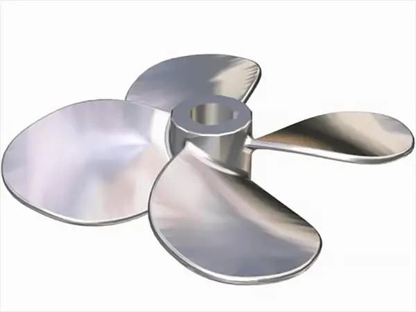
The result was an upgrade in the manufacture of underwater propellers, making them undetectable by the sonar of American spy ships. Therefore, the United States penalized Toshiba Corporation for violating the embargo on strategic materials.
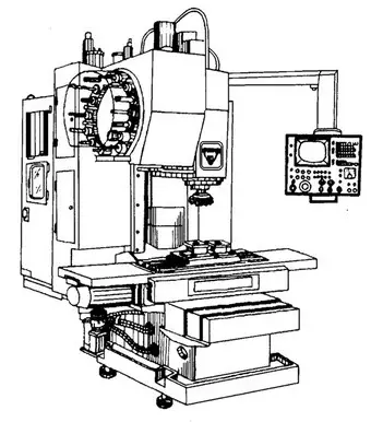
Machining centers have strong integrated processing capabilities. After a part is clamped once, it can complete a significant amount of processing, with high precision.
For batch parts of medium difficulty, its efficiency is five to ten times that of ordinary machine tools, especially because it can perform many tasks that ordinary machine tools cannot. It is particularly suitable for the production of complex shapes and high-precision units, or small-scale, multiple-variety production.
In modern manufacturing, precision machining is increasingly prevalent. State-of-the-art CNC machines and molds, which enable precise processing, are at the forefront of the manufacturing industry chain. The quality of mold products largely depends on CNC equipment.
Amid intense market competition, manufacturing demands shorter production cycles, higher processing quality, faster product retooling capabilities, and lower manufacturing technology.
To meet these conditions, more and more manufacturing companies are adopting state-of-the-art CNC machine tools – four- and five-axis processing machines.
We know that a three-axis machine tool has only three orthogonal axes of motion (commonly defined as X, Y, and Z axes) and can only achieve three directions of freedom of linear motion.
Therefore, it can process structures along the axis direction of the machining tool. Side frame resources cannot be processed. (The three-axis machine tool needs to design multiple sets of fixtures, install, locate and clamp multiple times, decompose the overall machining, thus prolonging the processing cycle and greatly reducing the quality.)
Unconstrained tools (or workpieces) have six degrees of freedom in space. The reality is that during metal cutting, enormous cutting forces and friction are generated between the workpiece and the tool.
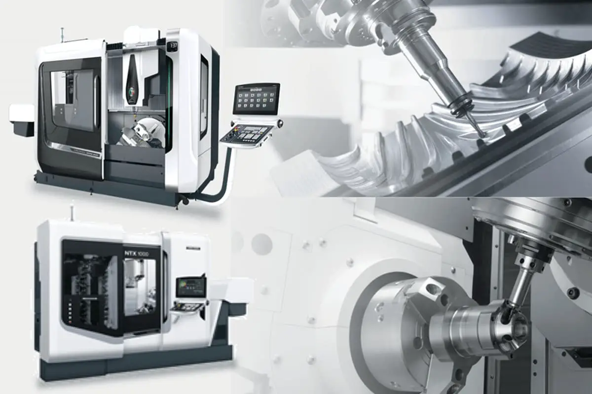
To prevent the position of the workpiece from moving, it must be clamped and fixed. Five-axis CNC machining refers to having at least five coordinate axes (three linear coordinates and two rotary coordinates) on a single machine tool, which can be coordinated and processed simultaneously under computer numerical control.
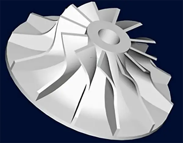
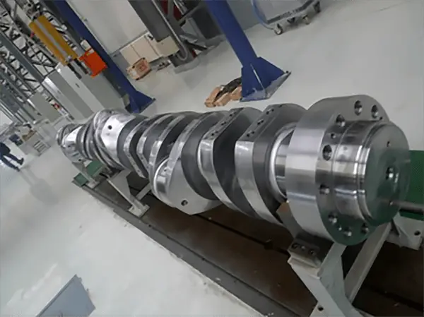
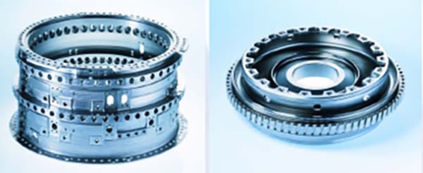
The five-axis linked CNC machine tool system is the only means to process impellers, blades, ship propellers, heavy-duty generator rotors, turbine rotors, large diesel engine crankshafts and more.
It is a high-tech, high-precision machine tool designed specifically for processing complex surfaces, exerting a significant influence on a country's aviation, aerospace, military, research, precision instruments, high-precision medical equipment industries, among others.
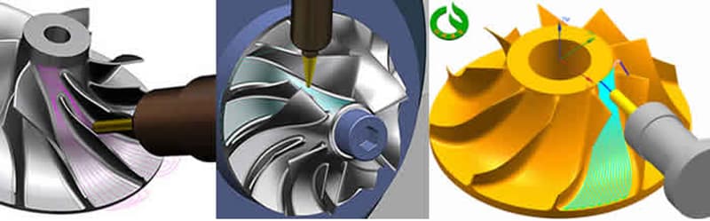
An impeller refers both to a wheel equipped with movable blades, which forms part of the rotor in impulse steam turbines, and to the assembly of the wheel and rotating blades mounted on it.
A steam turbine generator refers to a generator driven by a steam turbine. The superheated steam produced by the boiler enters the turbine, expands to do work, and turns the blades, which in turn drive the generator to produce electricity.
The spent steam after work is returned to the boiler for recycling through the condenser, water circulation pump, condensate pump, feed water heating device and other components.
Five Axis
The default coordinate system is a right-handed Cartesian system. The basic coordinate axes are three linear axes: X, Y, and Z. The rotational axes corresponding to each of these linear axes are denoted as A, B, and C, respectively.

Five-axis CNC machining refers to a machine tool with at least five coordinate axes (three linear coordinates and two rotational coordinates) that can perform coordinated movements for processing under the control of a computer numerical control system.
The “axis” in a CNC machine tool denotes an axis of motion, which can also be thought of as a spatial coordinate axis, like the XY axis in coordinates, with each axis of motion having an independent controller and motor drive system. .
That is, the CNC machine tool has five servo axes (excluding the main axis) that can interpolate simultaneously (all five servo axes can move at the same time to process a single part).
Structural Varieties
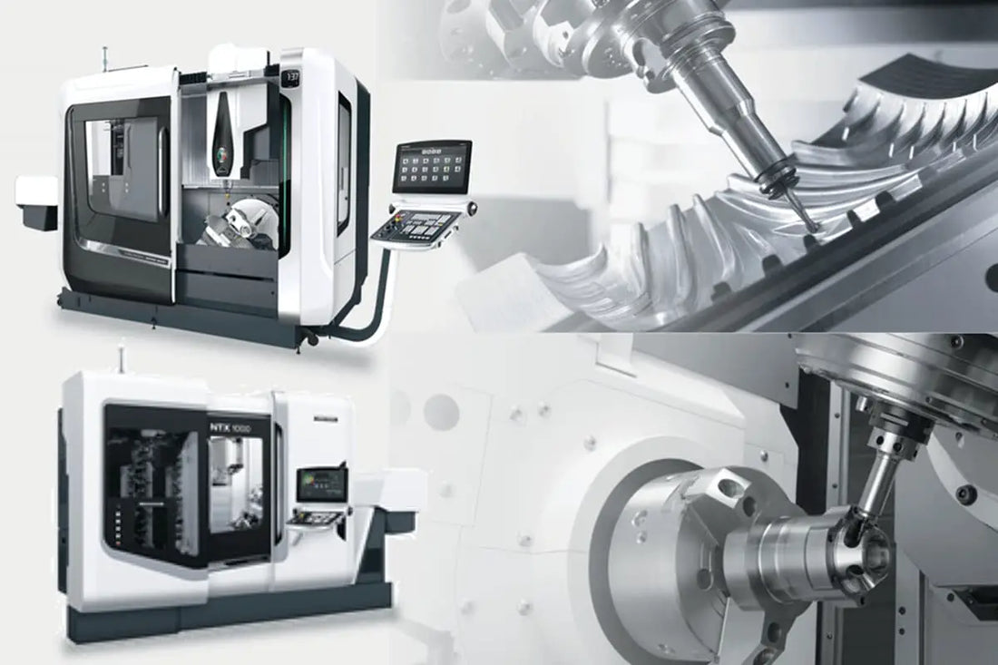
Five-axis CNC machine tools come in various structural forms, mainly divided into three main categories: worktable tilting type, spindle tilting type and a combination of worktable tilting type five-axis machining tools. work/spindle.
5 Axis CNC Machine Tool :
- Tilting work table type
- Tiltable spindle type
- Tilting worktable/spindle type
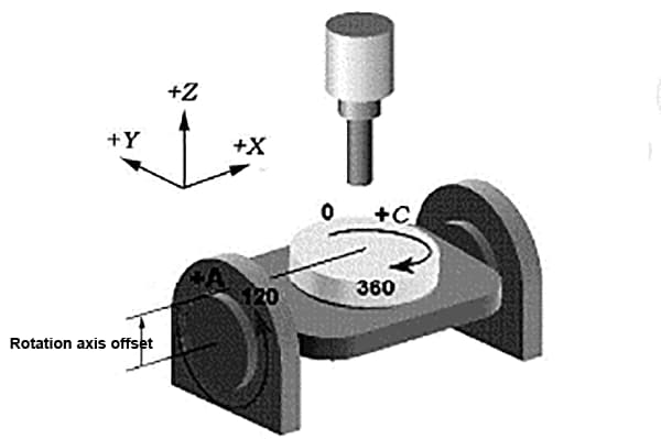
Inclined bench type
This refers to the inclined bench type. The bench placed at the base of the machine can rotate around the X axis, defined as the A axis, typically operating in a range of +30 to -120 degrees.
A rotating table is also installed in the center of the bench that can rotate around the Z axis at the depicted location, defined as the C axis, allowing a full 360 degree rotation.
The combination of A-axis and C-axis allows all five faces of the workpiece clamped to the workbench, excluding the bottom face, to be machined by the vertical spindle.
Minimum indexing values for the A-axis and C-axis are typically 0.001 degrees, which allows the workpiece to be subdivided at any angle, thus machining inclined surfaces and holes.
When the A axis and C axis are coordinated with the XYZ linear axes, complex spatial surfaces can be machined, which obviously requires support from cutting-edge numerical control systems, servo systems, and software.
The advantage of this configuration is that it has a relatively simple spindle structure with excellent rigidity and lower manufacturing costs.
However, the workbench generally cannot be designed too large, and its load capacity is somewhat limited, especially when the A axis rotation is greater than or equal to 90 degrees, as cutting the workpiece will exert a significant load. torque on the bench.
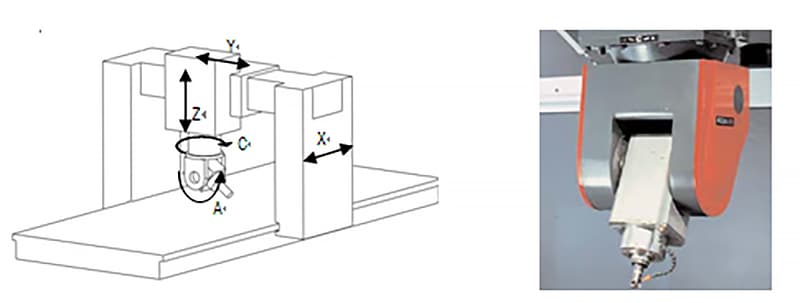
Inclined spindle type
The inclined spindle type features a rotating head at the front end of the main spindle, which can independently rotate around the Z axis by 360 degrees, thus becoming the C axis.
The rotating head also includes an A axis that can rotate around the X axis, typically reaching more than ±90 degrees, performing the same functionalities mentioned above.
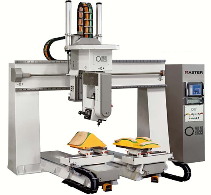
The advantage of this configuration is the flexibility it offers when machining the spindle; The worktable can be designed on a substantial scale, allowing the processing of huge aircraft bodies and engine casings in these machining centers.
Another significant advantage involves the use of a ball end mill for surface machining. When the tool centerline is perpendicular to the machining surface, the line speed at the tip of the ball end mill is zero, resulting in poor surface finish due to tip cutting.
However, by using a rotary spindle design that rotates the spindle at an angle to the workpiece, the ball end mill prevents tip cutting, ensuring a certain line speed and improving the quality of surface machining.
This structure is highly sought after for surface machining of high-precision molds, something difficult to achieve with a rotary table machining center.
To achieve high rotational accuracy, state-of-the-art rotary axes are equipped with circular grid scale feedback systems, enabling indexing accuracy within a few seconds.
Naturally, this type of spindle rotation structure is more complex and production costs are consequently higher.
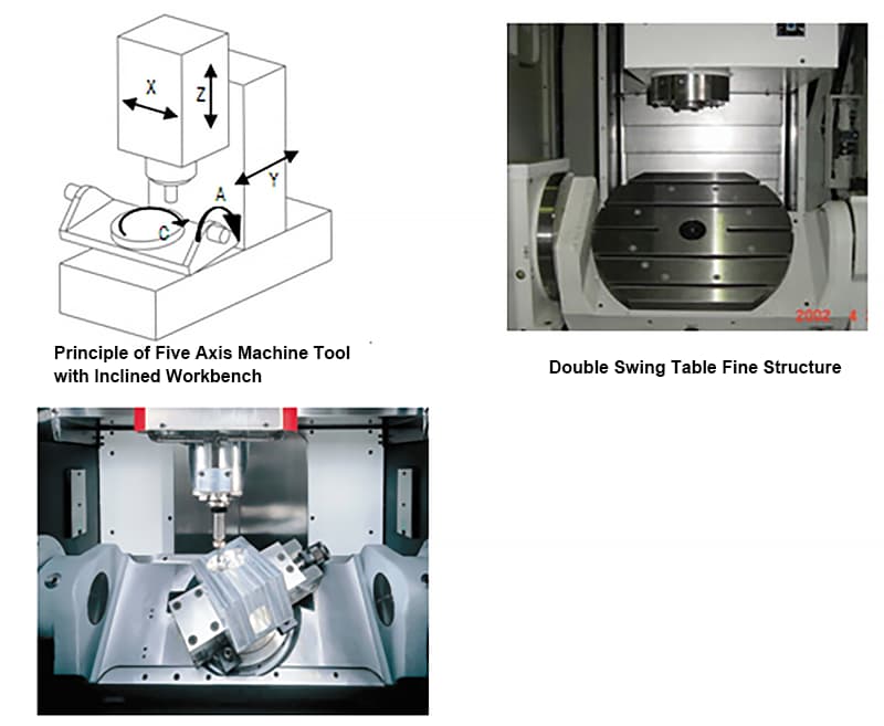
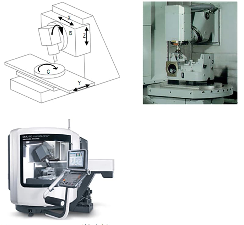
Work table/spindle tilt type
One rotational axis is on the tool side of the spindle head and the other is on the work table side. This type of machine tool has the most flexible arrangement of rotational axis structures, which can be any combination of the A, B, and C axes.
Most worktable/inclined spindle type machine tools are configured with a B-axis combined with a worktable rotating around the C-axis. This structural arrangement is simple, flexible, and shares the advantages of tilt-spindle type machines. spindle and tilt type work table.
The spindle on these machines can rotate to a horizontal or vertical position, and the worktable only needs to be indexed for positioning, making it easy to configure as a three-axis processing center capable of vertical and horizontal conversion.
By converting the spindle orientation and combining it with the worktable indexing, it is possible to perform pentahedron processing on the workpiece. This results in low manufacturing costs and practical utility.
Five-axis CNC machining application
The five-axis interconnected machining center is ideal for processing complex components that require a multitude of operations.
These components require the use of various types of conventional machine tools, numerous cutting tools and accessories, and often require multiple setups and adjustments for successful completion.
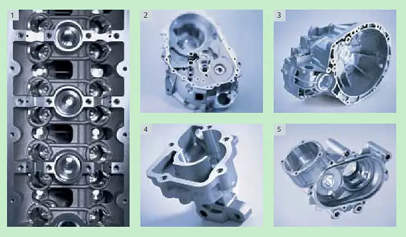
1. Cabinet-type components
Cabinet-type components often require multi-station holes and flat machining, with high tolerance demands.
Particularly, the shape and position tolerances are quite strict.
These components generally undergo milling, drilling, reaming, boring, broaching and threading operations, requiring numerous tools. The process is challenging on standard machine tools due to multiple fixtures and alignments, making it difficult to ensure machining accuracy.
When working on cabinet-type parts, the worktable needs to rotate several times to machine on four horizontal faces, making the use of a horizontal machining center appropriate.
2. Complex surfaces
Complex surfaces play a significant role in mechanical manufacturing, particularly in the aerospace industry. It is challenging, if not impossible, to manufacture complex surfaces using conventional machining methods.
These complex surface components include a variety of impellers, spherical shapes, various curved surface-forming crushers, propellers, underwater vehicle propellers, and other free-form surfaces. These components are most effectively processed on a five-axis machining center.
The cutter acts as an enclosing surface to approximate spherical surfaces. When machining complex surfaces with a machining center, the programming workload is substantial and most tasks require automated programming technology.
3. Irregular pieces
Irregular parts, characterized by their atypical shapes, often require mixed processing of points, lines and surfaces in multiple stations. These parts typically have low rigidity, making it difficult to control fastening deformation and ensure machining precision.
In fact, some parts have areas that are difficult to process with conventional machine tools. When working with machining centers it is prudent to adopt appropriate technological measures such as single or double clamping.
Utilizing the multi-station mixed processing capabilities of machining centers – spanning points, lines and surfaces – enables completion of many or all machining procedures.
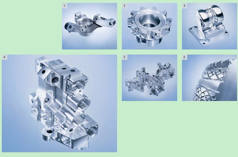
4. Flanged parts
Flanged parts, components with keyways, radial holes or end surfaces with a series of distributed holes, curved plates or shaft components such as flanged bushings, shaft components with keyways or square ends, and plate components with an extensive variety of holes, like different engine covers.
Vertical machining centers are suitable for disc parts with holes distributed on the end surface and curved surfaces, while horizontal machining centers can be chosen for those with radial holes.
5. Specialized processing
Once you have mastered the functionality of the machining center, a combination of appropriate jigs and specialized tools allows you to perform certain unique technical tasks.
This includes engraving text, lines and patterns onto metal surfaces. By mounting a high-frequency spark power supply on the main spindle of the machining center, linear sweep surface hardening on metal surfaces can be carried out.
Furthermore, equipping the machining center with a high-speed grinding head allows grinding of small modulus involute bevel gears and various curves and surfaces.