What is hydraulic blacksmith?
Hydraulic blacksmithing is a machine tool that combines multiple functions such as metal cutting, drilling, shearing and bending.
It is also called hydraulic steelworks.

It has the advantages of simple operation, low energy consumption and low maintenance cost.
It is the preferred equipment for metal processing in modern manufacturing industries (such as metallurgy, bridges, communications, electric power, military industries, etc.).
Blacksmithing is divided into two types: hydraulic blacksmithing and mechanical blacksmithing.
In this post we will focus on how hydraulic blacksmithing works.
Performance and features
Flat bar cutting, drilling and slotting can be performed on the machine within nominal specifications.
With extra equipment, the hydraulic hardware machine is capable of cutting, punching and bending into special shapes.
The steel machine adopted hydraulic drive system and has performance and overload protection device.
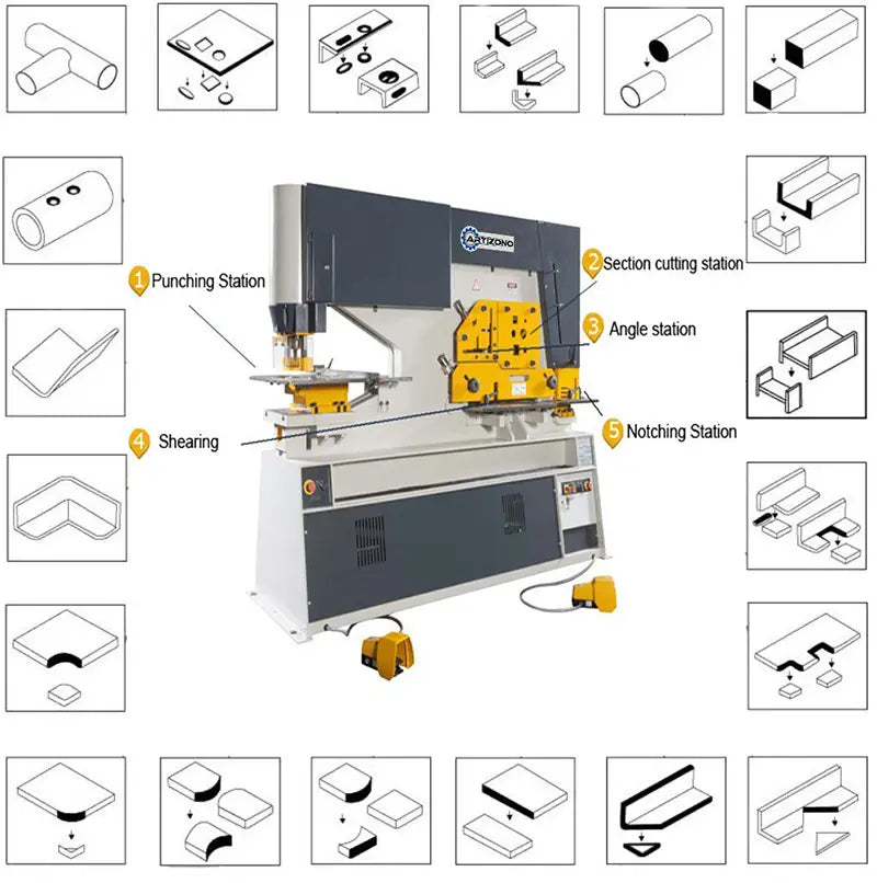
Structure of Hydraulic Ironworker
The bed can be seen in Fig.

The base of the sawmill consists of a body, seat, profile support, angle support and cutting table.
The body and seat are of welded construction, others are bolted which give the machine great strength and rigidity and allow easy disassembly during repair of the blacksmithing machine.
An adjustable pad to limit left-right movement of the blade is mounted in the left-right housing.
An adjustable bracket to hold the angle to be cut is installed on the angle cutting station.
With the square and round opening of various sizes on the section cutting blade, the iron working machine is capable of cutting various square and round bars.
The cutting table is equipped with a robust stand that is adjustable to any material thickness and with a stop finger to allow precise cutting of angles and flat bars at any angle.
Section cutting station (Fig. 2)

This station is equipped with solid frame blades as standard and has four openings for cutting angled, round, square and flat bars and notching steel sheets.
With extra tools in the square and round bar cutting openings, beam and channel bar cutting can also be carried out.
The beam is connected to the oil cylinder and the upper end is hinged with the frame.
Passing through the oil cylinder, the beam oscillates to make the cut.
The upper notch blade is fixed to the beam.
There are 3 lower blades that are separately fixed on the die seat with cabins, and the slotting blades on both sides can be adjusted to allow sufficient cutting clearance.
A side gauge and a back gauge are mounted on the slotting table to allow the plate to be slotted into the correct position.
Drilling (Fig. 3)

The punch is fixed to the lower end of the oil cylinder rod with lock nut, and the die is fixed to the adapter.
After the punch and die are aligned, the screws must be tightened.
For drilling long square and round holes, there is a guide on the side surface of the piston rod, in addition, along the round positioning groove is milled on the pad and the top of the punch to prevent the punch from being rotated.
With additional tools at this station, bending, tube notching, louver punching, large hole punching, channel, beam and web punching work can be carried out.
Hydraulic system
1) After starting the engine, the oil flow, which is compressed out of the pump (1), returns to the oil tank through the solenoid valve (4) to allow the pump to flush.
2) When turning the mode knob to the “SINGLE” position and pressing the pedal to drill the hole, the YV5b electromagnet is turned on, the hydraulic oil flows into the upper chamber of the drilling unit through the valve (3), the oil enters the lower chamber returns to the oil tank through the valve (3), so that the punch moves downwards to perform the puncture.
When the punch touches the limit switch at bottom dead center, the YV5b is turned off, the pump is set to be unloaded, then the punch is stopped. when the pedal is released and the YV5a is turned on, the hydraulic oil flows into the lower chamber of the hydraulic cylinder, the punch moves up to touch the limit switch at top dead center, then the YV5a is turned off and the punch is stopped at top dead center.
Similarly, when pressing the pedal for the cutting section, the YV7b is turned on, the oil enters the upper chamber of the oil cylinder for the cutting section, the oil in the lower chamber returns to the oil tank through the solenoid valve ( 3), then the blade moves down to do the cutting work.
When the blade touches the limit switch at low neutral, YV7b is turned off, the blade is stopped at neutral.
When the pedal is released, the YV7a is turned on, the oil enters the lower chamber from the oil cylinder to the cutting cylinder, the oil in the upper chamber returns to the oil tank, so the blade moves upward, as the blade touches the limit switch at the top dead center, it's there.
3) When turning the mode knob to the “INCHING” position and pressing the pedal to make the hole, the YV5b electromagnet is turned on, a part of the hydraulic oil enters the upper chamber of the oil cylinder to make the hole,
4) The maximum working pressure in the hydraulic system is 250kgf/cm 2 (24.5 MPa). The pressure adjustment range on the relief valve is 25MPa. The entire hydraulic system is protected against overload by the relief valve.
5) The steel machine is equipped with a pressure gauge which is used to check the pressure in the hydraulic system and adjust the pressure after replacing the hydraulic elements.
To use it, remove the final screw from the valve block, mount the pressure gauge and tighten it, then open the pressure gauge tap.
The pressure valve is shown on the pressure gauge during operation.
The pressure in the hydraulic system before delivering the machine has been properly adjusted to the delivery of the blacksmith machine has been properly adjusted to the maximum working value, so do not readjust as per your option.
Here are the drawings:
Blacksmith Hydraulic System Diagram 1
Blacksmith 2 Hydraulic System Diagram
Blacksmith 3 Hydraulic System Diagram
Blacksmith 4 Hydraulic System Diagram
Blacksmith 5 Hydraulic System Diagram
Blacksmith 6 Hydraulic System Diagram
Electrical system
(1. Introduction:
The hydraulic steel machine adopts the electrical system of three-phase AC and 208/220/440V 50HZ in the main circuit and single-phase 24V and 6V comes from transformer in the control circuit and signal circuit.
The section cutting station is equipped as standard with a pressure bottom for emergency stopping.
According to the machine technology request, the electrical system includes:
- “NORMAL” and “JOG” working modes are selected by turning the SA4 knob.
- The vertical stroke of the punch is controlled by limit switches SQ1 and SQ2. The section that cuts the up and down movement is separately controlled by limit SQ4 and SQ5, SQ6 and SQ5 are used to control the up and down movement of the notching cylinder. The change between notching and section cutting is controlled by SA5.
- SQ7 is located on top of the slotted part for secure protection. When you lift the safety cover, the section cutout does not move.
- The power supply and operation of the oil pump are indicated as HL1 and HL2.
(2) Engine starting and stopping:
When pressing the SB3 button, the oil pump motor is activated. When pressing the SB1 or SB2 button the engine is stopped. Short circuit and overload protection is performed by an automation switch.
(3) Operational process:
1) Single course
By turning the switch SA4 to the “NORMAL” position mode and stepping on the pedal SA6 or SA7, KA2 or KA4 obtains energy, at the same time YU5b or YU7b also obtains energy, so that the punching piston or the cutting piston section moves down. As soon as they touch limit switch SQ2 or SQ5, KA1 or KA3 receive power, KA2 or KA4 lose power the two pistons begin to return.
When touching limit switches SQ1, SQ4 or SQ6, feedback ends.
When the cylinder goes to the middle position. Release SA6 or SA7 to half position, KA2 or KA4 lose power. YV5b or YV7b lose power and the cylinder stops.
When you release the SA6 or SA7 pedal it will return.
2) Lunch adjustment
By turning the SA4 switch to the “JOG” mode position and stepping on the SA6 or SA7 pedal, KA6 is turned on, so that the punching piston or the section cutting and notching pistons move slowly downwards when they touch the limit switch SQ2 or SQ5, KA3 or KA6, YU5b or YU7b are off, so two pistons stop moving downwards when pedal SA6 or SA7 is released.
Two pistons cannot move upwards. To then return to top dead center, the SA4 switch must be placed in the “NORMAL” mode position.
3) Back measuring device
When placing the SA3 switch in the automatic position, turn the SA4 to the “NORMAL” position, placing the cutting material in feedback by pressing the SQ8 switch.
Section cutting starts to execute after time delay KT2 delays a few seconds when KA5 receives power.
When touching the SQ5 limit switch, the section cutting cylinder returns to top dead center. The cutting action is complete.
List of Electrical Elements
| Symbol | No. Name | Technical Data | Amount | Type |
|---|---|---|---|---|
| SB1-2 | push button | Red mushroom head | two | XB2-BS542C |
| SB3 | Home button | Green φ22 | 1 | XB2BW337B1C |
| SA3-5 | Limit switch | Black φ22 | 3 | XB2BD217 |
| SQ1-2 | Limit switch | two | Z-15GW22-B | |
| SQ4-6 | Limit switch | 3 | Z-15GW22-B | |
| QS | Load switch | V2 | 1 | VAR10 |
| KM1 | AC contactor | 24V | 1 | LC1-D3210 |
| KA1-4 | Intermediate reimbursement | 24V 5A | 4 | MY4 |
| FU1-4 | Fuse | 6A | 4 | C45N |
| FU5-6 | Fuse | 6A | two | C45N |
| HL2 | Signal lamp | 24V green | 1 | XB2-EV136 |
| YOU | Silicon Rectifier | 2A | 1 | KBPC20-10 |
| V | Overcurrent Suppressor | 1 | 3TX3-221A | |
| TC | Transformer | 440V 220V208V 250VA/29V 24V |
1 | JBK3-250 |
| SA6-7 | Foot switch | SFM-1 | two | |
| QS7 | Limit switch | 1 | 4MC-5000 | |
| QF | Motorized circuit breaker | 25-40A | 1 | GV2-M |
| QS8 | Limit switch | 1 | Z-15G-B |
Lifting, installation and preparation before test execution
Elevation
The hydraulic blacksmithing machine is equipped with a lifting ring, which is mounted on the top of the machine.
All lifting and maneuvering must be performed using this ring in conjunction with a suitably rated chain or sling.
The ring can be removed if desired after final location of the machine. Do not use chain and sling under the hardware machine.
Here are the drawings:
Hydraulic smithy installation diagram
The foundation with holes for anchor bolts must be prepared before installing the machine.
Only after the concrete foundation has hardened can the machine be placed on it.
Then, level the machine with a level gauge, mount the anchor bolts, pour liquid concrete on the bottom of the machine body and drill the holes for the anchor bolts.
After the concrete is hardened, level the working table of the machine's punching station (the permissible coherence is 100:0.2), and then tighten the anchor bolts.
Preparation before running the test
Clean and remove rust-proof grease from the die and machine blade, inspect that all parts, power wire and ground line are in good condition, and that all lubrication points should be lubricated.
Lubricating System

The hydraulic blacksmithing machine adopts a centralized lubrication system with a manual oil gun.
To increase the viscosity of the lubricant, the oil pump should be filled with a 4:1 mixture of #35 mechanical oil and calcium-based grease.
Operate the pump 2/3 times a day to ensure sufficient oil at all lubrication points.
Hydraulic Ironworker Adjustment
Punch
1) Puncture stroke adjustment (Fig. 3)
There are upper and lower limit switch stop blocks, which can be adjusted vertically, on the right side of the drilling station.
According to the desired position, the blocks are fixed to the guide rod, which is mounted on the piston rod and can be moved with it, using a fixing screw.
2) Punch & Die Adjustment
Loosen the die holder fixing screw and turn the knob to the “INCHING” position to make the piston rod in the punch cylinder move down by inches and the punch align with the die, ensuring a tight clearance. distributed among them.
Then, fix the support on the work table by the fixing screw and make the punch return to the top dead center, so that the adjustment before the punching operation is completed.
There are two holes for mounting dies or the big gusset hole is used to mount the die to make a large hole in the thin plate, another is used to mount the die to make a hole with a diameter of less than 30mm and to make a hole in channel flange and angle bar.
3) Adjustment of the retention unit
The clamping unit must be correctly adjusted to allow easy handling of materials.
In general, the distance between the bottom of the holder and the top of the die should be adjusted to 1.2 times the thickness of the plate to be punched.
To adjust the fixing, simply turn a left- or right-hand threaded nut connected to the hole unit.
4) Punch & Die Replacement
Loosen the fixed nut with a wrench, the punch can be removed.
After mounting a new punch, the nut is tightened (the mounting size of the ends of the various punches is the same to allow for easy replacement).
The matrix replacement process is very easy and simple.
Flat bar cutting

Whether cutting flat bar, profile cutting or chamfering, the blade clearance must be adjusted correctly first.
As shown in fig. 1there are six supports (4) in the right housing of the machine body.
By adjusting the screw and nut on the pads, proper blade clearance can be obtained between the left housing and the pads.
1) Blade gap adjustment
Adjustment screws are positioned around stable set screws to support and readjust the shear blades, accessible when the shear table is removed.
By turning these screws, adequate clearance between the stable and movable blades will be obtained.
A uniform gap must be maintained between them along the entire length of the blade.
In general, this gap should be 10% of the thickness of the sheet to be cut.
After adjusting, reassemble the shear table.
2) Replace the blade
The upper and lower blades have four cutting edges.
After turning the blades 4 times, you must resharpen or replace the new blade.
After replacing the readjustment, the clearance of the blades must be taken into account.
angle cutting

1) Blade gap adjustment
The angle cutting unit is equipped with a stable blade made up of two blades square to each other.
Adjustment screws are positioned around the blade set screws to support the cutting blades.
By turning the adjusting screws, proper clearance can be obtained between the stable blade and the movable blade on the carriage.
Even space between the stable and moving blades is important along the entire length of the blade and care must be taken to ensure that the stable blade is parallel to the moving blade.
This gap is generally 10% of the uniform thickness of the angle flange to be cut.
After adjustment, the angle bracket is assembled.
2) Replace the blade
Both the horizontal and vertical blades of the stable blade have four cutting edges.
Re-sharpen them or replace them with new blades after turning them four times.
The movable blade is fixed to a carriage using screws.
After resharpening or replacing dull blades, the blade gap must be readjusted.
Round and square bar cutting

1) Adjust the gap
There are two angle-shaped stop blocks, which support the stable blade and are fixed to the housing by screws, on both sides of the stable blade.
Adjustment screws are positioned around the set screws to adjust the clearance between the angled stop block and the housing, and the clearance between the support face nested in the angled stop block and the stable blade and the accommodation.
This is how the gap between the stable blade and the movable blade fixed to the carriage is adjusted.
After doing this, the profile support is assembled.
2) Replace the blade
Remove the carriage and loosen the angled stop block to replace the old blade with a new one. After replacement, the clearance must be readjusted.
Notch

1) Blade gap adjustment
When moving the bracket for the upper blade, it is placed parallel to that of the punch to allow adequate clearance, and then fixes the bracket to the table by the screw.
Adjustment screws are positioned around the set screw to adjust the blades on both sides of the punch, ensuring adequate clearance which is 10% of the thickness of the board to be cut.
Once this is done, the carving table is assembled.
2) Replace the blade
All die blades have four edges. After four replacements it is necessary to resharpen or replace with new ones.
The upper blade is fixed on the punch by the screw, loosen the screw and replace the old blade with a new one.
After replacement, the clearance must be readjusted.
Miter cut in 45º angle steel
Steel miter cutting at a 45º angle can be carried out in the cutting position shown in figure (1) BB.
Test run and operation of hydraulic blacksmithing

Testing and repair before operation
1) Pour sufficient filtered hydraulic oil (supplied by the user) into the oil tank.
2) Check that the blade clearance is adequate and adjust as necessary.
3) Turn on the power and check that the operation of the various electrical elements is correct, the installation is adequate.
Press and step on all buttons, limit switches, footswitch, etc., to observe the electromagnet actions and replay is helpful.
4) Start the engine to check that the operating direction is correct, that the pressure in the hydraulic system is in accordance with demands, that the overflow pressure at the overflow valve is in accordance with demands, and that the action of the overflow valve is switching is useful.
Test execution and preparation
After finishing all the preparation work before test execution, the test execution and operation process can be carried out.
The operational process is as follows:
1) By pressing the operation button and turning on the power supply, a green indicator lamp lights up to indicate that the electrical system has been turned on and operation can begin.
2) Start the engine, lubricate the upper and lower chambers of the punch cylinder and section cutting cylinder to check whether the punch and section cutting blade can reach the top and bottom dead center.
3) Idle cycle run test, inching test and single stroke for punching and section cutting in order.
During testing, the operating circumstances of various parts must be checked carefully. If any of them are out of service, after these problems have been resolved, further testing can be carried out.
4) Pressure should be added step by step in the load test. The number of cutting or drilling tests performed max. the capacity should not be less than 3 times.
Hydraulic smith safety and maintenance
The protective covers are proven in each season, no hands or tools should be stretched across the cover, and care must be taken at the following points:
1) The operator must be familiar with the machine's operating manual and have certain operating techniques.
2) Electrical insulation and grounding must be in good condition.
3) Punching and notching work must not be carried out simultaneously.
4) Do not perform overload operation. (Material tensile strength=450N/mm, material hardness=HB180).
5) Keep all blade tips sharp.
6) No welding scars or burrs should remain on the surfaces of the plate to be punched or cut.
7) To ensure safe drilling and cutting work, the clamping unit must be adjusted according to any material thickness within the cutting capacity of the machine.
8) After replacing the blades, their clearance should be checked again and adjusted as necessary.
9) Regularly check that the connections of all parts are in good condition. If an abnormal circumstance is found, the machine must be stopped to be repaired in time.
10) Lubricate all lubrication points according to the working period to avoid damage to working surfaces.
List of wear parts and hydraulic blacksmithing parts to be purchased
| No. | Name | Specifications. | Amount |
|---|---|---|---|
| 1 | Mango | 1 | |
| two | Friction Block | 3 | |
| 3 | Stop executing the block | 1 | |
| 4 | YX Shape Sealing Ring | D165 | two |
| 5 | O-shaped sealing ring | 130×3. 1 | 1 |
| 6 | -to do- | 165×5. 7 | 1 |
| 7 | YX Shape Sealing Ring | d125 | 1 |
| 8 | Dustproof Ring | 125 | 1 |
| 9 | YX Shape Sealing Ring | D200 | two |
| 10 | O-shaped sealing ring | 135×5. 7 | two |
| 11 | -to do- | 200×5. 7 | 1 |
| 12 | YX Shape Sealing Ring | d125 | 1 |
| 13 | Dustproof Ring | 125 | 1 |
| 14 | SF-1 Composite Material Composite Bearing | 5560 | 1 |
List of accessories equipped with the hydraulic blacksmithing machine
| No. | Name | Specification or Type | Amount |
|---|---|---|---|
| 1 | Pedal | A13-11 | 2 units |
| two | Key for interlock device | 2 units | |
| 3 | Hex key | S=3-19 | 1 set |
| 4 | Hook-shaped wrench | D=90-95 | 1 unit. |
| 5 | Unloading cock | 1 unit. | |
| 6 | Manometer Unit | 1 set | |
| 7 | O-shaped sealing ring | 130×3. 1(GB1235-76) | 1 unit. |
| 8 | -to do- | 165×5. 7(GB1235-76) | 1 unit. |
| 9 | -to do- | 200×5. 7(GB1235-76) | 1 unit. |
| 10 | -to do- | 135×5. 7(GB1235-76) | 2 units. |
| 11 | Dustproof Ring | 125 | 2 units |
| 12 | Composite Material SF-1 Bearing | 5560(SF-1) | 1 unit. |
| 13 | oil gun | Capacity:200cm³ | 1 |
PACKING LIST
| No. | Name | Specification or Type | Amount |
|---|---|---|---|
| 1 | Operations manual | 1 copy | |
| two | Test certificate | 1 copy | |
| 3 | Packing list | 1 copy | |
| 4 | Pedal | SFM-1 | 2 units |
| 5 | Earth Screw | M16×300 | 4PCS |
| 6 | Key for interlock unit | 2 units | |
| 7 | Manometer Unit | 1 set | |
| 8 | Hook-shaped wrench | D=90-95 | 1 unit |
| 9 | High cook | 1 unit | |
| 10 | Hex key | S=3-19 | 1 set |
| 11 | O-shaped sealing ring | 130×3. 1(GB1235-76) | 1 unit |
| 12 | -to do- | 165×5. 7(GB1235-76) | 1 unit |
| 13 | -to do- | 200×5. 7(GB1235-76) | 1 unit |
| 14 | -to do- | 135×5. 7(GB1235*5. 7) | 2 units |
| 15 | Dustproof Ring | 125 | 2 units |
| 16 | Composite Material SF-1 Bearing | 5560(SF-1) | 1 unit |
| 17 | oil gun | Capacity:200cm | 1 |