This is a complete operation manual for the swing beam cutting machine which is also a very popular hydraulic cutting machine.
Standard Features of Hydraulic Cutting Machine
The hydraulic guillotine was designed to cut metal-steel sheets, with a capacity based on sheet strength of 450N/mm2.
Adjust the plate thickness if you are cutting other materials with different strengths.
The machine has a welded plate structure, which provides easy operation and reliable performance.
Cutting is powered by hydraulic pressure and return is controlled by a nitrogen gas cylinder, which helps protect the machine against overloads.
The machine can be equipped with digital display system or numerical control system as per customer request.
A blade clearance indicator is also provided for convenient and quick adjustments.
The machine is equipped with a lighting alignment device, and the cutting stroke can be adjusted to improve the efficiency of cutting narrow plates.
Additionally, front support arms and a rear gauge are provided. The rear meter is mechanically transferable and its position can be displayed numerically or controlled by an NC controller via encoders, with micro-adjustment via handwheel. The front support arms are equipped with rulers.
A rolling material support ball is provided on the worktable to minimize fish deflection with plate bars and reduce frictional resistance.
A security fence has been installed to ensure safe operation.
The structure of hydraulic cutting machine
Machine f Branch
High rigidity steel welded plate has two cylinders fixed to the left and right vertical post.
A cutting board is installed on the work table for convenient adjustment of the lower cutting board, ensuring that the space between the upper and lower cutting boards is aligned. A feeding ball is also installed on the work table for quick and convenient operation.
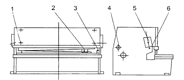
Cutting frame
The high rigidity welded plate is supported on the eccentric socket (9) and driven by the left and right cylinders and the stroke cylinder to complete the cutting process through pendulum repetition. (See Figure 1). The vertical surface of the top cut support is curved to maintain the alignment of the gap between the top cut and the low cut.
Pressure device (Calm)
It consists of pressure feed cylinders installed on the support plate in front of the machine frame. The flow of oil into the feed cylinder under pressure creates pressure that pushes downward against the pulling force of the tension spring (18), firmly clamping the pressure plate. After cutting is completed, the cylinders are reset by the pulling force of the tension spring. Pressure increases with plate thickness. (See Fig. 3)
Front meter and rear meter
Front meter:
The work table is equipped with a valve display on the ruler, allowing you to adjust the movable bar to the desired valve. Cutting thin steel plates can be done conveniently at the front gauge. The back gauge (see figure 5) is fixed to the cut plate and moves up and down with it.
The rear meter is adjusted by a 0.55Kw motor, which reduces torque through a gear and drives the control rod. By pressing the “+” or “-” button, the meter can be adjusted forward or backward. If the desired valve cannot be achieved through mechanical adjustment, the handwheel (50) can be rotated to obtain the required valve, making back gauge adjustment convenient and reliable.
The standard range of the back gauge is 20 to 750 mm. If the length of the cutting board is greater than the maximum back gauge distance, the back gauge (43) can be removed to its minimum position and the board can be lifted using the inclined surface of the support frame (47), allowing the cutting any length of board. (See Fig. 4)


Hydraulic cutting machine installation
Packaging/Shipping of hydraulic cutting machine
All machines that leave the factory are packaged with a squared arm and foot panel tied to the hand guard. Working tools and an operating manual are packed in a box.
All exposed surfaces of the machine are coated with a rust inhibitor, which can be easily removed with kerosene or solvent.
Lifting Hydraulic Cutting Machine
Use only approved and safe wire ropes to lift this machine from the two lifting points located on both sides of the machine. (See Figure 5)

Foundation
All of our shears are designed to be installed on a foundation. See attached foundation drawing for details.
Installation
This hydraulic cutting machine must be properly leveled for optimal cutting performance. This can be achieved by using a high quality leveling gauge in the plate attachment area.
Before leveling, ensure you have five base plates (measuring at least 150 x 150 x 9 mm) placed under the machine feet to prevent the leveling screws from penetrating the concrete floor.
Once the machine is level, secure its position by filling the space beneath and around its feet with a cement mortar mix.
Electrical installation
Make sure the local power supply is compatible with this hydraulic cutting machine before connecting any electrical power.
Connect the power cord to the lower left side of the electrical panel. Some machines may require a neutral wire.
The electrical diagram of hydraulic cutting machine
Here are the drawings:
Electric diagram
4.1 The following steps must be carried out by specialized personnel and are the responsibility of the owner.
- Check the hydraulic cutting machine's nameplate and make sure its wiring matches the wattage available at your facility.
- If the required power does not meet machine specifications, contact your electrical supplier for assistance.
- Make sure the machine's power supply is protected by fuses so that it can be completely disconnected for repairs.
- Please refer to the attached electrical drawings as different controllers may have different diagrams.
4.2 All operation buttons are fixed to the front control panel, with the exception of the SF pedal. Symbols for each function are displayed above the buttons.
The steps to operate the digital display system are as follows:
- Open the electrical box door and turn on switches QF1 and QF2 to turn on the machine. Close the electrical box.
- Press the SA1 key button to turn on the control circuit. The HL1 light will illuminate to indicate the machine is on.
- Press the SB4 or SB5 buttons to move the back meter forward or backward.
- The position of the rear gauge is displayed on the SICK mechanical display. SQ3 and SQ4 limit switches are installed at the maximum and minimum strokes of the back gauge, with a standard travel range of 20 mm to 750 mm.
- Press the SB3 lighting button to turn on the pump motor, which can be heard running.
- Use the SA3 button to select the cutting mode, manual or automatic.
- The illumination light is indicated by SA4. Turn to 1 to start counting and to 0 to stop counting.
Hydraulic system
Clean the hydraulic oil
Cleaning the hydraulic oil in the hydraulic system is extremely important. Cleaning the oil tank is crucial.
When changing the hydraulic oil, it is necessary to remove the oil tank cap. Clean the bottom of the tank with a towel (do not use cotton thread) and then wash with cleaning gasoline or kerosene.
Due to limitations of the tank cap, the arm may not reach the end of the tank. In such cases, wrap the towel around a bamboo or stick to clean every corner.
To remove any dirty oil, loosen the leaking plug or brake valve.
Use a cleaning towel to completely dry the sides and bottom of the tank until it is clean.
If necessary, wrap a cloth around the welding seam or hard-to-clean areas to remove any dirt, then replace the cover.
Choose hydraulic oil
The viscosity rating of hydraulic oil corresponds to its average viscosity at 40°C. If the hydraulic system operates at higher pressure and temperature and at a slower speed, a higher viscosity rating should be chosen.
It is recommended to use anti-wear hydraulic oil with ISO VG46# classification (average viscosity of 46 mm2/s at 40°C). If the machine is to be operated at temperatures below 5°C for a long period, it is recommended to use hydraulic oil with ISO VG32# rating.
Using the machine at very low temperatures (below -5°C) is not recommended, but if necessary, the machine should be stopped for a while. An oil heater can be installed in the circuit if necessary.
Under normal operating conditions, the oil temperature should not exceed 70°C. If necessary, an oil cooler can be installed.
Fill the oil
The oil used must be clean. Tighten the air filter nut and fill it through the air filter.
If you are using filter filling equipment, you can open the oil tank cap and fill it directly.
Watch the oil gauge, when the ram stops at Top Dead Center, the hydraulic oil should fill 80-90% of the spaces in between.
Start the machine and let it idle first, then operate it at maximum stroke to expel any air bubbles in the hydraulic circuit.
Hydraulic schematic drawing
The operating rule of the hydraulic system is as follows:
The cropping frame drops:
When magnetic discharge valve 3 is energized, pump 2 extracts hydraulic oil, which flows through magnetic discharge valve 3 and into the seals and upper area of the main oil cylinder. The retaining piston moves down to press the metal plate against the spring force and the oil pressure begins to rise.
When the pressure reaches the nitrogen gas pressure in the stroke cylinder, the cutting frame moves down to cut.
The cut structure returns:
When the cutting frame reaches bottom dead center, the magnetic iron YV1 of the magnetic discharge valve 3 loses power due to a limit switch, and the cutting frame rises due to the pressure of the nitrogen gas cylinder.
At the same time, the oil in the upper area of the main cylinder flows back to the oil tank through the magnetic discharge valve.
The retaining piston also rises due to the spring force and the oil returns to the oil tank through the magnetic unloading valve 3.
When the cutting frame reaches top dead center, a cutting cycle is completed.
6. Standard control equipment
| home button | To start the main engine and control circuit. |
|---|---|
| stop button | To stop the operation of the main motor and control circuit. |
| Auto/Man mode selector switch | Select work mode |
| In Auto mode | -One step on the pedal, the cutting frame will continue cutting. |
| -You can control the cut just with the pedal. | |
| In manual mode | -One step on the pedal, the cutting frame will only make one cut. |
| -Adjust the cutting stroke by returning the rotary knob on the panel. | |
| Pedal | Push to command the cutting blade downwards and release to raise the upper blade support in AUTO mode. |
| lighting light | Work light to illuminate the cutting blade area, operating on single-phase 220V, 50Hz power supply. |
Adjustment and operation of hydraulic cutting machine
Adjusting the gap between the blades of the hydraulic cutting machine
Blade clearance is crucial to both the quality of the cut and the life of the blades. Adjust according to the clearance adjustment chart below.
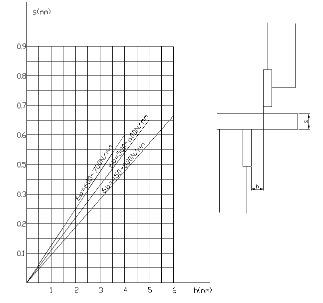
To adjust the gap (see Figure 2), it is necessary to loosen the tightening screw (4), then turn the handwheel (3) to the desired value, which must be calculated based on the thickness of the plate, and finally tighten the screw (4).
There is a ball valve (located on the right side of the machine, outside the cylinder) that is used to measure the gap between the upper and lower blades.
For more details: In manual mode, when the cutting frame reaches bottom dead center, quickly close the oil circuit, making the cutting frame remain at bottom dead center. Then slowly turn on the ball valve, making the cutting structure rise step by step along the entire stroke. This will allow you to measure the gap between the blades.
Hydraulic Cutting Machine Operation
7.2.1 Machine Preparation
(1) Remove the square arm and pedal from the handguard area. Attach the squaring arm to the left side of the machine table using screws and the two side holes. The arm must be close to the electrical panel.
(2) Clean the components of any dirty oil, taking care to ensure the ball valve is in the open position.
(3) Lubricate all necessary areas.
(4) Fill the oil tank with 200L of HL46 hydraulic oil for each 12mm model machine.
(5) Connect the ground wire, turn on the power, and check the operation of all electrical components.
7.2.2 Starting the Machine
(1) Press the 'START' button and release.
(2) The 'engine running' indicator light should come on.
(3) Change the mode selector from 'MAN' to 'AUTO'.
(4) Step on the pedal, causing the cutting structure to descend and make a cut.
(5) If the cutting frame does not lower, the engine is likely running in the wrong direction. Turn off the power and reverse either of the two phase wires to restart the engine.
(6) The upper blade support will rise and stop when it reaches the limit switch.
7.2.3 Motorized back gauge
(1) The motorized back gauge display must be accurately adjusted at the factory and must match the distance from the back gauge bar to the cutting edge.
(2) Press the '+' button to bring the rear meter bar back. The reading will increase and stop when it reaches the maximum travel limit switch L/S 3.
(3) Press the '-' button to bring the rear meter bar forward. The reading will decrease and stop when it reaches the L/S 4 minimum travel limit switch.
(4) Back gauge parallelism must be set at the factory, but can be calibrated as needed.
(5) Move the rear gauge bar back to remove the anti-rust coating before cutting.
Observation:
(1) The pressure table must be turned on during cutting and the pressure must be checked if it appears incorrect. The overflow valve may need to be adjusted.
(2) If any unusual noise or overheating of the oil tank occurs during operation, the machine must be stopped immediately. The oil tank temperature must not exceed 60°C.
Hydraulic Cutting Machine Troubleshooting
The machine cannot start
- Check the input power supply.
- Check whether the Emergency Stop is enabled.
- Check the transformer output.
The machine cannot cut
- Check if the limit switch is engaged.
- Check that the engine rotates at the correct speed.
- Check that the pedal cable is not broken.
- Check that the microswitch inside the pedal is working.
Ram chattering in downward motion
- Counterweight adjustment pressure is a little too high
- Just loosen the fixing screw a little to decrease the setting.
The machine operates alone
- Make sure the microswitch inside the pedal is not damaged.
- The pedal cable may be shorted to each other.
The failure and resolution of the hydraulic system
| Lack | Cause | Solve |
|---|---|---|
| Pressureless hydraulic system and actionless cutting structure | 1. The magnetic switching valve plug is a bad connection. | 1. Inspect the plug. |
| 2. The valve core is stuck by debris or becoming rough. All butterfly valve holes of the coincidence valve cannot flow. | 2. Disassemble the valve and clean. | |
| 1. The cutting frame returns slowly or cannot rise to neutral | The nitrogen gas pressure is not sufficient. | Supply nitrogen gas to add pressure |
| 2. The action of cutting the structure and fixings is disharmonious |
Hydraulic cutting machine maintenance
Lubrication and Hydraulic Oil
This machine uses grade 46 hydraulic oil and should only be refilled or replaced with oil of the same grade, such as:
- FIAT-HTF 46
- ENERGOL HLP46
- ESSO NUTO H46
- SHELL-TELLUS S68
- TOTAL-AZOLLA 46
Lubrication program
The hydraulic oil in this machine must be changed after the first 1,500 hours of operation and drained completely from the oil tank to remove any impurities that may have entered during assembly. The oil filter must also be changed and replaced with an oil filter of the same type. Subsequently, oil changes must be carried out every 5,000 working hours.
Additionally, all lubrication nipple points should be lubricated every two weeks, which are located on the rear gauge assembly.
| No. | Name | flow | Internal time (h) | Type and brand |
|---|---|---|---|---|
| 1 | One upper point and one lower point on each return cylinder. | Small | 16 | Ca lubricating oil ZG-3 GB491-65 Mechanical oil N46GB443-84B |
| two | One point to the left and one point to the right of the rear stop sliding nut | Average | 8 | |
| 3 | Two fulcrums for oscillating the upper knife frame, one on the left and one on the right | Small | 24 | |
| 4 | One to the left and one to the right of the clearance shaft sleeve | Small | 48 | |
| 5 | Each point on the piston rod of the left and right cylinders | Average | 8 | 4# lithium carbon Q/SY1000-65 |
| 6 | Each on the left and right cylinder filler block | Average | 8 |
Observation:
- Mix 50% calcium-based lubricating oil with 50% mechanical oil for use.
- Mix 30% Lithium-Carbon lubricating oil with 70% mechanical oil.
- Replace the oil tank once every six months.
Replacing the shear blade
The upper and lower shear blades are identical and interchangeable. To make the cutting frame lower to bottom dead center, use the ball valve and turn off the machine.
First remove the lower blade and then the upper blade. Loosen all small retaining screws on the upper blade support.
Clean the blades and blade housing/seat. Attach the upper blade first and then the lower blade. If necessary, tighten the small set screws on the upper blade bracket to decrease blade play. Remember to check the minimum clearance and adjust the small set screws to close the blades as needed.
CAUTION: Always hire qualified and experienced personnel to perform this work as damage to the blades/shearing machine or personal injury may result.
Shear Blade Grinding
The shear blade is rectangular in shape and the upper blade has two cutting edges, while the lower blade has four cutting edges. You only need to resharpen the blade after all two or four edges have been used.
When resharpening, remember to grind only the thickness and not the height of the blade. Loss of grinding thickness of the shear blades may result in the need to close the upper blade holder by adjusting the screw on the tension screw (next to the blade quick release lever).
Upper and lower blades
(Tool drawings See attached drawings)
Hydraulic cutting machine main construction and safety prevention
Observation!
This section is only applicable to machines with special requirements and should not be referenced to other machines.
To ensure the safety of people and equipment, we design safety equipment. The operator must not modify, remove or disconnect safety equipment.
10.1 Light Beam/Laser Beam
There is light beam or laser (depending on customer request). If the operator blocks the light curtain, the safety module will be activated and the ram cannot move downward to avoid injury to the operator.
10.2 Safety Grid
There is a safety grill located on the side and rear of the machine to keep the operator away from dangerous areas. The safety network is connected to the electrical system via a safety switch. If the safety grille is opened, the electrical system will start and the machine will not be able to operate.
10.3 Emergency Stop
There is an emergency stop button located on the handle control station and the overhead control station. In case of operation error or accident, pressing the emergency stop button will cause the machine to stop all actions.
10.4 Hydraulic System
To prevent dangerous falling of the ram, the system has a safety lift valve. The shift valve and safety lift valve cores have a check sign. If the valve core is abnormal, the check signal will stop the electrical system to prevent injury from falling. If the shift valve and safety lift valve cores cannot be reset, the valve should be checked.
10.5 Troubleshooting
Normal operation is safe. If a strange accident occurs, or during maintenance or repair of the machine, lock the safety grille, press the emergency stop button inside the uprights and seek help. If your hands or any other part of the body becomes trapped by the punch or sheet, press the emergency button, check the condition and restart the machine. Change the operating mode to the “inch” position, then press the handle return button and the ram will return, allowing you to remove the clamped parts.