Pittsburgh blocks photos of old machines
 |
 |
 |
|---|---|---|
| Multifunctional Nip Machine | Combined Elbow Narrowing Machine | Combined Nip Machine |
Model and Technical Parameters

Main Function and Performance
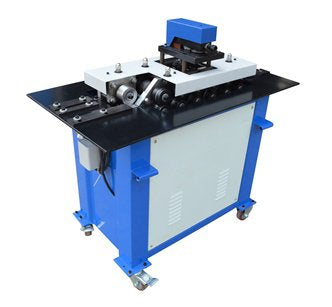
- Pittsburgh lockformer machine is specifically designed to produce various square or rectangular ventilation ducts.
Our Pittsburgh locking machine is SA12-SA15HB.
Forming steel sheet with a thickness of 0.5-1.5 mm (listed separately on page 2 – Machine photos). - With features of small size, light weight, easy to move, simple and reliable operation, Pittsburgh lock forming machine is especially suitable for on-site manufacturing of exhaust ducts in industries and mining, enterprises, hotels, shopping malls.
- Use cases

Figure 1
Pittsburgh locking machine structure
It consists of the following three parts:
- A. Work table
- B. Transfer and training
- C. Elbow head

Figure 2
1) For single flat mouth, tighten the second top screw on the right discharge port and loosen the right angel screw.
Matters need attention :
① For SA-12 — SA-15HB Pittsburgh locking machine, the thickness of side plate, double screw screw④ and disc-shaped spring(4a) are adjustable. Four screws ③、④ are fixed.
A. Work table
The trunk is a welded shell structure which is made of angle steel and thin steel plate, with a working table panel fixed on the top of the plate, the panel is equipped with horizontal input positioning plates ①、② and four fixed exit positioning plates, see figure 2.

(Fig. 3)Transfer System
B. Transportation and Training
The entire drive section is an open gearbox.
Passed through gear shafts 11, 12, 13, 14 and gears 16, 17, 18, 19 to the forming section, gear 19 separately drives Ⅲ down gear 35 and Ⅳ down gear 35, then through the multiple bridge gears driving the entire movement system.
Pittsburgh locking machines are generally equipped with 6 to 7 pair forming shafts, each pair shaft is equipped with a 35 driving gear and two left and right columns or three left, center and right columns of rolling coils.
(Fig. 3) is a comprehensive transmission diagram, however, not all machines are equipped with all components listed in fig, such as machine SA-12、SA-15、SA-12H、SA15 without spool 201-214 .
C. Elbow head
Structural principle: (a fig.2 on top), through the bevel gear (5), (7) driving gear (10) and rolling spool (8) and (9), the workpiece will be placed into the spool opening and forming a fan. piece molded at a certain height of the bone at right angles, as shown in fig.1: E=(1)+(6)

Figure 4
The elbow head is a dedicated part installed on the top of the Pittsburgh Locking Machine (as shown in fig.2:C), mainly used for right angle bone, that is, bending the plate into a fan shape at a certain height of the right-angled edge (see fig.4).
Connect this kind of right angle and “ ![]() ” shaped plate with flange edge to make angle pipe connector.
” shaped plate with flange edge to make angle pipe connector.
Each mode of the Pittsburgh locking machine will be equipped with an elbow component according to user demand, for example, change SA12C to SA12BC.
Adjustment and use
Pittsburgh lock forming machine can be used for connecting or bending, but it cannot roll, so when using the machine, some clearance is required between the upper roller and the lower roller, and the gap is approximately the minimum thickness of the plate plus 0.1-0.2 (3).
The clearance has been adjusted before delivery, users should not arbitrarily turn the stop screw (3) and fixing nut (4) and disc spring (4a) (as shown in fig.2 and 5).

Figure 5
In case of change in clearance due to loosening of bolt (3), nut (4), or caused by other reasons, first loosen nut (4), and place a pair of spacers of the same thickness as ![]() between the four leftmost roller groups, then adjust the stop screw (3) until the four gaps are basically parallel, relock the nut (4),(
between the four leftmost roller groups, then adjust the stop screw (3) until the four gaps are basically parallel, relock the nut (4),( ![]() =Min. plate thickness+0.1-0.2mm), if it is minimum thickness, place the spacer and leave a small space.
=Min. plate thickness+0.1-0.2mm), if it is minimum thickness, place the spacer and leave a small space.
Right angle roller 300 pieces, manually adjust the roller and disc-shaped spring, keep the sheet thin.” ![]() ” in 90° shape.
” in 90° shape.
②Bone shape adjustment:
Loosen the screws (1) and (2) on the inlet positioning plate and move the guide plate in the horizontal direction to widen or narrow the forming parts. Wide plate ![]() narrow board
narrow board ![]() wide plate
wide plate ![]() narrow board
narrow board ![]() .
.
③Use and adjustment of the elbow (fig. 7)
First, bending the part head 90°, length 15mm, height H (SA15-HB H=10mm, other 8mm) (as shown in fig.6).
Then insert end B between (8) and (9) in the narrow direction (as in fig.7), then tighten the screw (40), turn on the machine, forcefully push the plate together with the guide rotor onto the roller of bearing.

Electrical schematic diagram (three-phase)
Here are the drawings:
Electric diagram
Guidance rule adjustment schematic diagram
Here are the drawings:
Guidance Rule Adjustment Diagram


1comment
gostaria de um orçamento da SA-15HB