Manual loading and unloading tasks are labor-intensive, pose a risk of workplace injury, and are less efficient.
Furthermore, they do not guarantee consistent product quality, failing to satisfy companies' high-quality, high-volume production requirements.
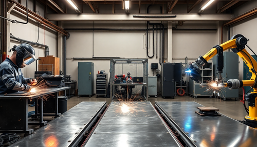
Our company has implemented an automated production line for forming sheet metal for door frames, integrating multiple machines operated by industrial robots. By pairing these robots with sheet metal equipment, we can automate processes such as material feeding, positioning, coordination with sheet metal machines, handling and finished product unloading.
This significantly reduces labor and material costs and increases production efficiency.
The door frame is an essential component of anti-theft security doors. Precision in the formation of the door frame directly impacts the security level and performance specifications of the door.
According to the national standard GB17565-2022 “Technical Conditions for Anti-Theft Security Doors”, door frames must meet the following specifications:
1. Based on safety grades B, C and D, the thickness of the door frame steel plate should be 2.00mm, 1.80mm and 1.50mm respectively. The steel used must meet the tolerances specified in Table 1.
| Allowable deviation from the rolling method | Tolerance thickness/mm | 1.50 | |
| 2:00 | 1.80 | ||
| Allowable deviation of cold rolled steel sheet | -0.15 | -0.14 | -0.12 |
| Allowable deviation of hot rolled steel sheet | -0.17 | -0.17 | -0.15 |
2. The diagonal dimensions of the frame and door leaf, as well as the tolerances of the frame groove and the outer dimensions of the door leaf, must meet the requirements of Table 2.
| Size/mm | <1000 | 1000~2000 | 2000 ~ 3500 | >3500 |
| Tolerance range/mm | ≤2.0 | ≤3.0 | 4≤ | ≤5.0 |
3. The overlapping width between the door leaf and the frame should not be less than 8mm. The door frame and leaf, or other parts, may have an anti-intrusion device installed. The device and its connection strength must withstand a 30 kg sandbag impact test three times. After testing, no breakage or detachment should occur.
The national standard GB17565-2022 has set higher requirements for the material and precision of door frames. Traditional rolling processes do not meet these precision demands.
To solve this, our company developed a fully automated production line using a pressing process for metal forming. This not only meets national standards, but also increases product yield, increases production efficiency and reduces labor and material costs.
Automation Production Line Overview
Equipment introduction
1. The automated door frame sheet metal forming production line consists of ten six-axis robots, seven press brakes, two punching and cutting machines, two three-in-one feeders, a conveyor, a cutting machine and a cabinet of safety, covering a total length of 65 meters. (See Figure 1)

2. Material feeding is done by roller. Two products on one side share a feeder, while a product on the opposite side uses a separate feeder. (See Figure 2)

3. The picking method employs a modular suction cup effector, versatile enough to handle a variety of products and easily adjustable. (See Figure 3)

4. Basic features of robotic units include:
- A Chinese information interface, suitable for robot trajectory debugging and PLC program debugging.
- Display of fault information, operational data and production details for each unit.
- Operational guidance and self-diagnostic information for each unit.
- Each robotic unit and pressing machine interconnect during operations. PLC synchronization programs and sliding position detection of sheet metal equipment ensure that robots load and unload smoothly without interfering with sheet metal machines.
Production process
Based on the structure of the door frame product, our company analyzed the manufacturing processes of its three components, totaling ten operations.
Step 1 : A three-in-one feeder sends the sheet metal to the cutting machine. Once it reaches the set length, a signal is sent and the cutter cuts the sheet metal. The machine then waits for the robot to retrieve the cut material, as shown in Figure 4.

Step 2 : Six-axis robot 1 transports the cut sheet to the press brake mold A to start bending. Meanwhile, the robot returns to fetch another spreadsheet, as illustrated in Figure 5.

step 3 : The six-axis robot 2 transfers the component from press brake A to press brake B. Upon receiving the signal, the machine starts the bending process. The robot then retrieves another part, detailed in Figure 6.

Step 4 : After the press brake B completes bending, the six-axis robot 3 places the workpiece inside the punching and edging machine C to begin the punching and edging process. The robot later searches for another part, as illustrated in Figure 7.

Step 5 : Once punching and edging are complete, the six-axis robot 4 moves the part from Machine C to Press Brake D. The bending process begins upon signal, with the robot returning to pick up another part. See Figure 8 for reference.

Step 6 : After bending in Press Brake D, the six-axis robot 5 transfers the component to Press Brake E. Bending resumes after a signal warning. Simultaneously, the robot retrieves another part, as highlighted in Figure 9.

Step 7 : Following the bending process in Press Brake E, the six-axis robot 6 moves the component to Press Brake F, where bending takes place after signaling. The robot then searches for the next part, shown in Figure 10.

Step 8 : After bending in press brake F, the six-axis robot 7 places the component back in press brake C for further bending. The robot then collects another part, illustrated in Figure 11.

Step 9 : After the Press Brake G bending operation, the six-axis robot 8 switches the component from Press Brake C to Press Brake H. Bending continues after a signal, with the robot searching for the subsequent part, detailed in Figure 12.

Step 10 : After the press brake H completes bending, the six-axis robot 9 moves the sheet metal bender component to the punching and grinding machine I to begin punching, as seen in Figure 13. After punching, the robot six-axis 10 transports the component to the assembly line, marking the completion of a production cycle.

Central Control System
This automated line uses a centralized CPU control structure. The entire control system employs strict hierarchical control. Without permission from the main operating station, the equipment cannot operate independently.
Various smart sensors and readers communicate via buses with corresponding PLCs or remote I/O units. This includes on-site operating stations, field equipment detection units (proximity switches, photoelectric switches, etc.), other field input devices, and field actuators (such as inverters, electromagnetic gaps, etc.).
The interlocking signals between the automation line PLC and the pressing machine PLC are connected via buses or I/O, while the line PLC exchanges data with the robot control system via a bus.
Line-wide operating modes
This automated production line operates in two modes: “Manual” and “Automatic”. Each operating station has an “Auto/Manual” mode switch.
1. Automatic Mode :
A standard production mode with continuous sequential operations. In this mode, the sheet metal forming equipment operates in a single stroke, stopping at the top dead center of the slider awaiting commands.
During the operating cycle of sheet metal equipment, robots collect slider position data and complete loading and unloading actions.
2. Manual Mode :
A maintenance and debugging mode that performs all equipment actions following predetermined production trajectories.
Conclusion
The automated door frame sheet metal forming production line developed by our company produces 7 to 8 parts per minute, achieving component precision standards.
Compared to traditional production methods, efficiency increases by 30%, part qualification rates increase by 25%, labor costs fall by 90%, and material costs are reduced by 15%.