In the early stages, manual line production used stamping dies, which resulted in a high rate of rework and scrap due to iron chips falling from the edges of the dies. This seriously impacted our quality, cost and efficiency.
To solve this problem, we have established a technical research group focused on iron chip cutting and falling, and have conducted extensive research on the problem of iron chip falling. The results of this research were successful.
The objective of the automobile industry's main engine factory is to achieve high quality while maintaining low cost.
The production rate of the manual stamping production line in the old factory was 3 to 5 strokes per minute (spm). However, after upgrading to an automatic production line, the production rate increased to 6 to 10 spm, resulting in double production efficiency and significant cost savings in production and operations.
One challenge we faced was that the molds used on the manual line were not sufficient to support the demands of the automatic line. To overcome this, the molds used in the manual line had to be transformed and updated to meet the requirements of automatic closed line production.
The problem of iron chips falling out of the stamping die
The main purpose of converting the manual stamping line mold into an automatic mold is to solve the problem of iron filings falling during cutting.
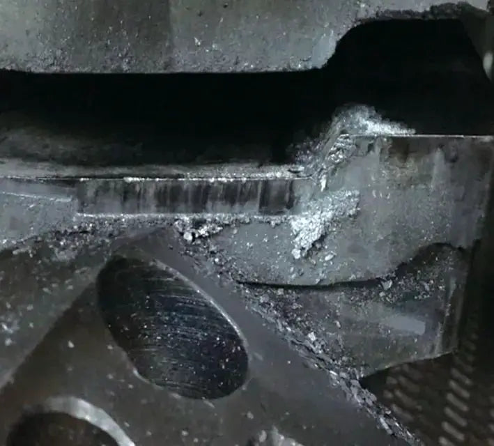
Iron writing in stamping production tends to adhere to the surface of the mold and parts (as shown in Figure 1), causing indentations on the surface of the parts (as shown in Figure 2).
When indentation defects are detected by the end-of-line quality inspector, at least 7 parts must be reworked or discarded.
This not only severely impacts the appearance quality of stamping products, but also increases the cost of subsequent operations.
Eliminating iron writing produced by cutting dies is a major challenge in stamping production.
By optimizing and transforming the die structure of the manual production line, we can effectively reduce the amount of iron writing produced during production, and there will be no significant crushing of residual iron writing on the surface of stamped parts.
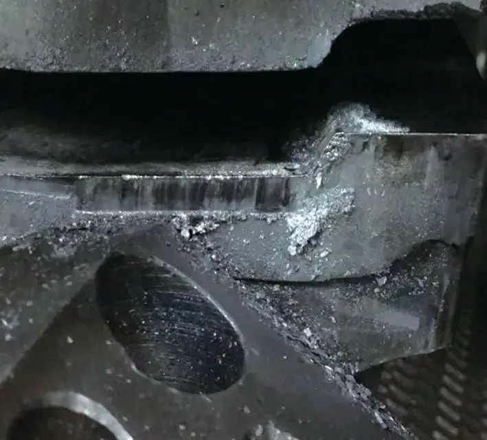
Fig. 1 accumulation of iron filings in the lower block of the die

Fig. 2 crushing on the outer surface of stamped parts
Blade structure optimization and grinding
The optimization and correction of the cutting and punching knife block can meet standards, maintain stable production, minimize the generation of iron filings, and effectively solve the problem of iron writing.
⑴ The optimization and improvement of the straightening tool block includes the following steps (as shown in Figures 3 and 4):
① Smoothing of the “wavy” portion of the reference surface;
② Transform the positive cone of the cutting surface into a 90° vertical plane;
③ Edge sharpening through repairs;
④ Keep the reference surface at a distance of 10mm.
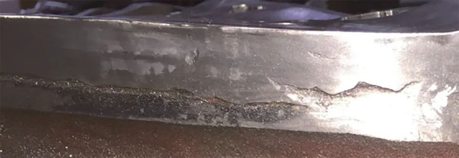
Fig. 3 before direct repair tool block grinding
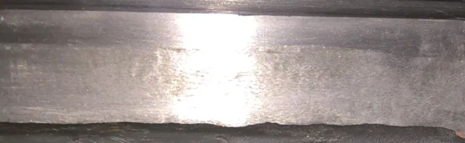
Fig. 4 after direct repair tool block grinding
⑵ Punch optimization and improvement include the following steps (as shown in Figures 5 and 6):
① Reduce the original intake from 10 mm to 5 mm;
② Lowering the peripheral edge of the upper part of the punch and flattening the middle protuberance;
③ Shaping and polishing the edge and circumference of the punch.
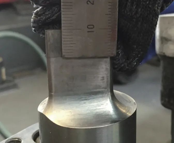
Fig. 5 Excessive puncture intake
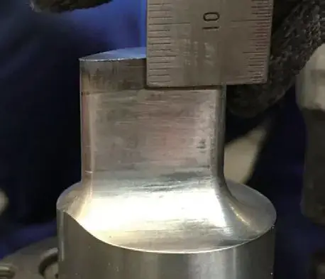
Fig. 6 Reasonable puncture intake
⑶ Optimization and improvement of blade clearance and its distance from the pressing plate include:
① Grind and align the gap of the red tipped blade to ensure uniform and adequate spacing (as shown in Figures 7 and 8);
② Increase the gap between the cutting edge and the pressure plate from 0 ~ 0.1 mm to 0.5 mm ~ 0.7 mm (as shown in Figures 9 and 10).
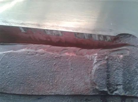
Fig. 7 blade clearance is too small
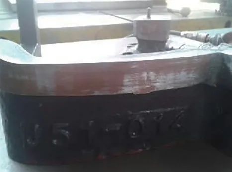
Fig. 8 uniform blade clearance
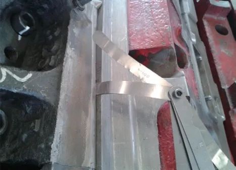
Fig. 9 the gap between the cutting edge and the contour of the pressing plate is small
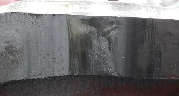
Fig. 10 the gap between the cutting edge and the contour of the pressing plate is uniform
(4) The optimization and improvement of residual knives includes the following steps (as shown in Figures 11 and 12):
① Reducing the gap between the residual knife and the knife block from 7mm to 1mm;
② Reducing intake from 12mm to 4mm;
③ Switch from a non-empty knife to an empty knife.
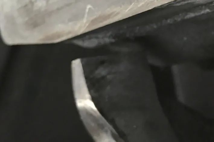
Fig. 11 knife residue before grinding
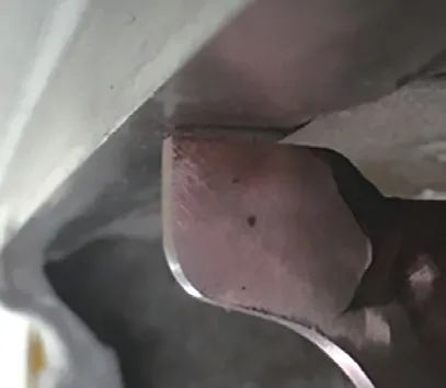
Fig. 12 after knife residue grinding
Rectification of the central pressing structure
Optimizing and improving the pressing surface of the pressing core includes the following steps (as shown in Figures 13 and 14):
① Reduce the pressing control surface of the pressing core from a maximum of 40cm to less than 20cm.
Reducing the pressing area helps to minimize recoils, as even small amounts of iron filings will not be introduced into the mold;
② Increase pressing core lapping rate from 75% to more than 95%;
③ Smooth and polish all pressing surfaces.
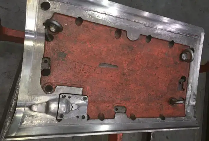
Fig. 13 before grinding the pressing core profile
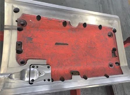
Fig. 14 after grinding the pressing core profile
A ventilation hole with a diameter of 30 mm was added to the local closed area inside the pressing core to maintain consistency with the external air pressure, thus avoiding the problem of absorbing iron debris due to the negative pressure inside the mold during pressing. production (as shown in Figures 15 and 16).
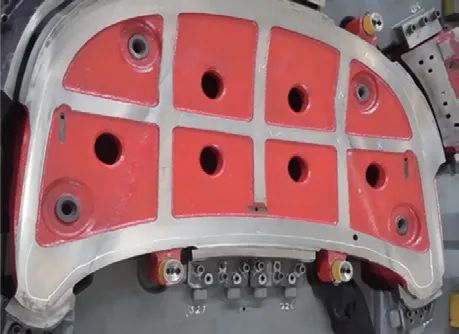
Fig. 15 before adding the vent hole to the pressing core
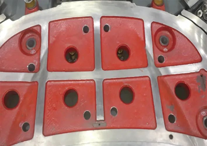
Fig. 16 after adding the ventilation hole to the pressing core
Add a ventilation hole for drilling
Optimizing and improving the addition of ventilation holes in the punch includes:
① Increasing the number of ventilation holes on the punch surface from 230 to 290, resulting in an increase of 26%.
Ventilation holes are located in areas with large surfaces and smooth arc transitions.
The size of the ventilation holes is φ6mm, which is consistent with the original size (as shown in Figures 17 and 18);
② Smoothing and polishing the convex surface of the model.
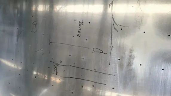
Fig. 17 drill before adding ventilation hole
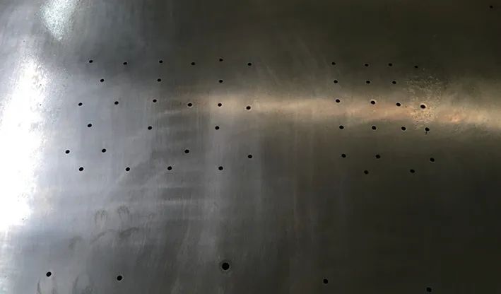
Fig. 18 after adding the vent hole to the punch
Conclusion
By optimizing and improving the cutting edge, pressing core and punch structure, the process parameters meet the requirements of the cutting process and minimize the generation of cutting iron writing, thus avoiding the crushing of parts and molds by the iron writing.
In the last 8 months of production, the retreat rate decreased from 8.5% to 3.1% and remained stable for three consecutive months with a clear improvement.
To solidify achievements and seek continuous improvement, we take two actions:
Firstly, we apply success stories to the structural design stage of new molds to minimize the problem of chips and falling iron writing as much as possible.
Secondly, we establish guidelines for the maintenance of stamping dies with iron inscriptions falling from the edges of the dies, which are controlled through the system and process to ensure the stability of the stamping dies during production and operation and reduce the number of products unskilled caused by iron writings.