I. Construction Preparation
1. Preparation of Materials
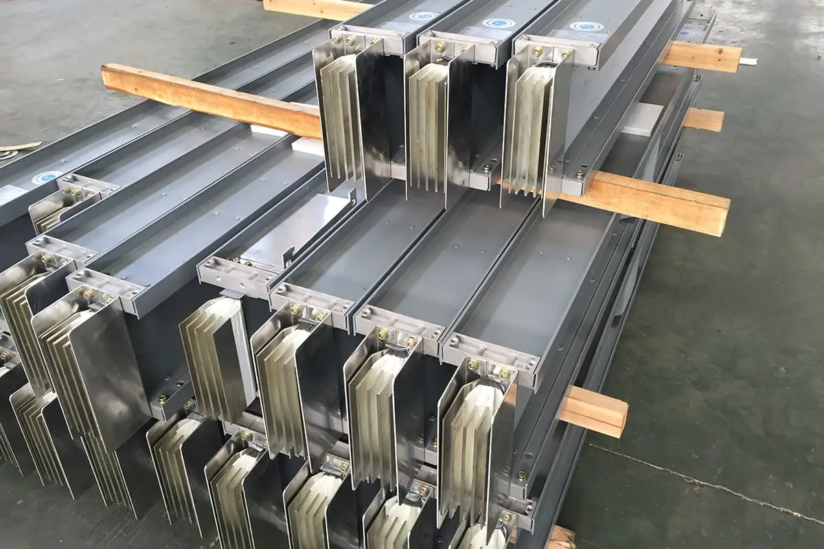
1) Closed plug-in bus ducts
2) Various specifications of steel profiles, clamps, all kinds of screws, washers, etc.
3) Camphor, paint, welding rods, etc.
2. Equipment Preparation
1) Main installation equipment: hydraulic lifting truck, scaffolding, lifting machine, pulley, large rope, bench vise, steel saw, hammer, electric drill, electric hammer, welding machine, hydraulic pipe bender, adjustable wrench , manufacturer's special tools, torque wrench, etc.
2) Main testing equipment: steel square, steel tape measure, level, insulation resistance tester, etc.
3. Working Conditions
1) Internal locations suitable for installing closed and plug-in busbars are now dry, and all architectural decoration work at the installation location should be completed, with all doors and windows in place.
2) The installation of internal closed busbars must be carried out after the completion of the basic construction of piping and air conditioning works, to avoid damage to the busbars during the construction of other specialties.
3) The scaffolding for high-altitude work has been erected and accepted by the safety technology department.
II. Construction process
1. Process Flow
Equipment unpacking check
→ Fabrication and installation of support
→ Installation of closed and pluggable bus duct
→ Startup testing and inspection
2. Key points of construction
1) Bus duct unpacking inspection
① Closed and plug-in busbars must be accompanied by a factory certificate of conformity and technical installation documents. Technical documents must include rated voltage, rated capacity, test reports and other technical data.
② The packaging and shell must be in good condition, the specifications of the bus duct must meet the requirements, and all types of steel profiles, clamps, various screws, washers and other accessories must be complete.
③ Each section of the bus duct provided in the set must be clearly marked, with complete accessories, without deformation of the shell and without internal damage.
④ The screwed overlapping surface of the included and pluggable bus ducts must be tin-plated. The overlapping surface must be flat and the tin layer must not have a bumpy, peeling surface or exposed parts.
⑤ The inner surface of the cabinet and plug-in bus duct shell should be painted with matte black paint, and the outer surface should be painted with light-colored paint.
2) Bus duct support manufacturing
The shape of the bus support is determined by the bus installation method. There are three installation methods for the busbar: vertical installation, horizontal side installation and horizontal suspension installation.
Brackets can be provided by the manufacturer according to the user's needs or can be manufactured by the user. The manufacture and installation of supports must be carried out in accordance with the product’s design and technical documentation. If there is no provision in the project and technical documentation, they can be manufactured and installed in accordance with the following requirements.
The supports must be made of angle iron, channel steel or flat steel according to the structural type of the construction site. The preferred shapes are “I” type, “U” type, “L” type and “T” type.
Brackets must be processed in accordance with the selected model and measured dimensions. The cutting of steel angles and channels must be sawed or punched and chamfering is necessary. The use of electric and gas welding cutting is strictly prohibited. The maximum processing size error should not exceed 5mm.
Drilling the bracket must use a bench drill or a hand drill. The diameter of the hole must not exceed the diameter of the fixing screw by 2 mm. The use of electric and gas welding to make holes is strictly prohibited.
The threading of the support rod must be processed using a threading machine or die. Cross-threading or thread breaking is not permitted, or a threaded rod may be used instead of a threaded support rod.
Metal supports and accessories manufactured on site must be galvanized or painted as necessary. In places where conditions are not available or requirements are not high, camphor and gray paint can be applied.
3) Installation of bus supports and brackets
The installation location of closed and pluggable bus supports should be determined according to the needs of the bus layout.
When straight sections of closed and plug-in busbars are placed horizontally, they must be fixed with brackets or hooks. The spacing between fixed points must meet the design requirements and regulations of the product's technical documentation, generally 2~3m, and it is advisable to be 2m for currents above 1000A.
When the closed and pluggable busbar is fixed vertically along the wall, a fixed support must be used. For vertical installation of closed and plug-in busbars on building slabs, spring brackets must be used as support. For closed and plug-in busbars with lower current capacity (400A and below), spring supports can be placed on the slabs every two layers, and for 400A and above, they need to be supported on each layer.
Supports must be added at the corners and connection points of the box (panel) for built-in and plug-in busbars. For closed busbars and plug-ins placed vertically, when entering the box and the end is suspended, a support must be used for fixing.
Any installation of closed, pluggable bus brackets and brackets must be accurately positioned, horizontally and vertically straight, and securely fixed. When installed in rows, they must be well arranged and evenly spaced. Flat washers and lock washers should be added to the fixed bracket bolts and the thread should be exposed 2 to 4 turns.
1. Attaching expansion screws to brackets
Supports installed in buildings must measure the most accurate position of the support according to the direction of the bus path, drill holes in the determined positions and first fix the expansion screws for installing the supports.
When drilling holes to install expansion screw bushings, a drill with the same outer diameter as the bushing should be used, and the difference between the diameter of the drilled hole and the outer diameter of the bushing should not be more than 1 mm.
2. Installation of I-shaped steel angle brackets
The I-shaped steel angle bracket is suitable for horizontal installation of busbars on walls. The bracket is recessed into the wall using the pre-embedded method. The embedding depth of the steel angle support is 120 mm and 150 mm. The exposed length of the angle steel when the busbar is installed vertically is the busbar width plus 140 mm, and when the busbar is installed horizontally, it is the busbar height plus 160 mm, as shown in Figure 1.
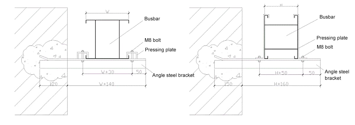
(a) Supports for installing vertical busbars; (b) Supports for horizontal bus installation
W—Bus width;
H—Bus height
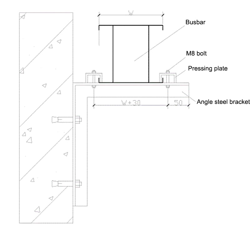
3. Installation of L-shaped steel angle brackets
L-shaped steel angle brackets are suitable for installing horizontal busbars on walls or pillars. To fix the L-shaped steel angles to the wall or pillar, use M12×110 expansion screws, as shown in Figure 2.
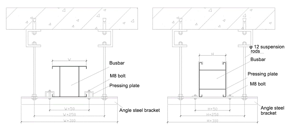
4. Installation of Hangers on Slabs
Closed and plug-in busbar lifting includes various types, including single-support and double-support types. Depending on the location of the bus lifting, the method of installing the supports also varies. The double rod bracket is shown in Figure 3 for horizontal busbar installation on the floor slab. If the strength is satisfactory, an internal expansion screw can also be used.
4) Closed plug-in bus installation
When the closed plug-in bus is placed horizontally, the distance to the ground should not be less than 2.2 m. When placed vertically, measures must be taken to prevent mechanical damage to parts below 1.8 m from the ground, except when placed in dedicated electrical rooms (such as distribution rooms, electrical shafts, technical layers, etc.).
The included plug-in bus must be placed correctly according to the segment diagram, phase sequence, number, direction and brand.
① Inspection before bus assembly
Before assembling the busbar, each segment must be checked to verify that the casing is complete and free from damage or deformation.
The busbar must also be tested for insulation, segment by segment, before assembly. Check whether the insulation resistance value meets the factory requirements. You can use a 500V megohmmeter for testing. The insulation resistance value of each bus section should not be less than 20MΩ. If necessary, a voltage withstand test can also be carried out with a test voltage of 1000V.
② Vertical bus installation
When lifting the bus, bare steel cables must not be used for lifting and tying.
For vertical installation of the busbar along the wall (limited to small amperage busbars), door-type brackets can be used for installation. The busbar can be installed on the door support in two ways: flat fixing and side fixing, as shown in Figure 4. The busbar pressure plate is provided by the busbar manufacturer.
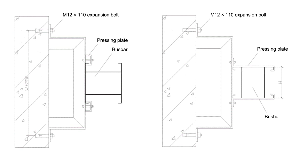
(a) The bus is installed horizontally on the support; (b) The bus is installed laterally on the support
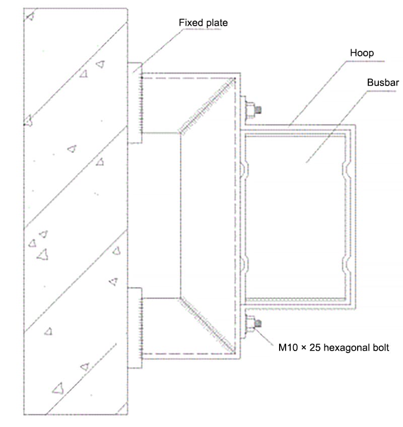
For 100A~500A BMC type closed busbars, vertical installation is shown in Figure 4. The busbar is secured to the support using a clamp and M10×25 hex screw.
When the closed busbar is installed vertically on the building floor, the spring bracket must be installed in the busbar slot before installation, and then the busbar slot must be installed in the pre-defined steel channel, as shown in Figure 6.
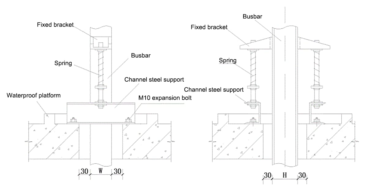
The function of the spring support is to fix the bus groove and support the weight of each layer of the bus groove. Only bus slots longer than 1.3 m can be equipped with spring supports. When installing the spring bracket, the position of the bus connection must be considered in advance. Generally, when the busbar is installed vertically through the slab, the center of the busbar joint should be 700mm above the slab.
③ Horizontal busbar installation
The horizontal bus installation sequence must start from the beginning to the middle and then to the end. There are also two installation methods, flat and lateral, on different types of bus supports and hangers. The installation of the busbar and support/suspensor is fixed with a pressure plate.
The flat installation of the busbar is fixed with a flat pressure plate, and the side installation of the busbar is fixed with a side pressure plate, all of which are provided by the manufacturer. The flat pressure plate for flat installation of the busbar is fixed with an M8×45 hexagonal nut, and a φ8 flat washer and spring washer must be used on the side of the nut. The side pressure plate for busbar side installation is fixed with an M8×20 hex nut, and a φ8 flat washer and spring washer are also used on the side of the nut. Closed and plug-in busbars can also be fixed to the steel angle bracket using a flat or vertical clamp.
④ Bus Lifting
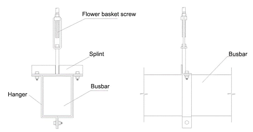
For suspended installation of embedded and plug-in busbars, in addition to being fixed with a pressure plate, they can also be installed with a lifting clamp and lifting tool, as shown in Figure 7.
5. Bus connection
When connecting the closed busbar, the busbar must be concentric with the housing, with an error of no more than 5mm. When connecting section to section, the adjacent busbar and housing must be aligned and the connection must not cause mechanical stress to the busbar and housing. The connecting flange at the wall penetration, the screws between the housing and the base, and the screws in each connecting part of the housing must be tightened with a torque wrench, and each joint surface must be well sealed.
The bus connection adopts high-insulation, arc-resistant and high-strength insulating plates to separate each conductive copper line to complete the bus plug-in, and then uses insulating screws covered with epoxy resin to fix, ensuring isolation reliable bus connection.
When connecting the bus section to the section, first remove the connection cover, insert the two bus slots together, pass the connection screws and insulating sleeves through the connection hole, and after the bus plug-in is tightened, use a torque wrench to tighten the connecting bolts, or double nut breaking is required to break, and a worker identification card is pasted at the connecting point, and then cover the connecting cover, at this point the two bus slots have been connected.
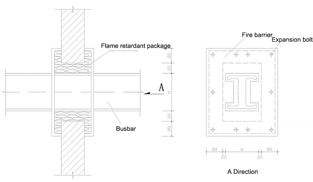
Closed and plug-in busbar connections should avoid busbar supports, and busbar connections should not be made where they pass through floors or walls. When the bus passes through the fire wall and fireproof floor, fire insulation measures must be taken. As shown in Figure 8.
The plug-in distribution box must match the bus slot with the plug-in holes. During the installation of the closed plug-in busbar, the distribution box must be placed in a safe and convenient location for operation and maintenance. It is advisable that the lower edge of the distribution box is 1.4-1.6m above the ground.
For the connection between the included plug-in bus and the low voltage distribution shield, a starting line box (input protection box) must be used at the starting end of the bus. The headbox is connected to the distribution screen with a transition bus, which is a copper line, and the bus connections at both ends must be tinned.
For the connection between the closed plug-in bus and the equipment, a steel conduit must be laid openly from the bus plug-in distribution box to the equipment junction box (box), and the two ends of the steel conduit must be threaded. On the internal and external walls of the box (box), a nut and a mouth guard must be used to tighten the conduit and the box (box). From the equipment junction box (box) to the equipment electrical control box, ordinary plastic pipes or flexible metal pipes can be used.
6 Closed plug-in bus grounding
The metal casing of the included plug-in bus must only serve as a protective casing and must not be used as a protective earth wire (PE wire), but the casing must be grounded. Each bus section must be interconnected with a strip of braided soft copper of at least 16 mm so that the bus casings are interconnected.
7 Test execution and acceptance of project delivery
After installation of the closed plug-in bus, it must be tidied up and cleaned, the insulation resistance values between phases and with respect to ground must be tested using a megohmmeter, and records must be kept. The bus insulation resistance value must be greater than 0.5 megohms.
If it meets the requirements after inspection and testing, it can work without load for 24 hours without any abnormal phenomena, then delivery acceptance procedures can be carried out. If the included plug-in bus cannot temporarily operate under power after installation, clear signage must be installed at the location to prevent damage.
III. Quality standards
1. Main control items
1) The insulator base, bushing flange, protective net (cover) and busbar support and other exposed conductors must be reliably grounded (PE) or zeroed (PEN). They must not be used as continuation conductors for grounding (PE) or zeroing (PEN).
Inspection method: Visual inspection.
2) The installation of the closed plug-in busbar must comply with the following standards:
1 The busbar and housing must be concentric, with an allowable deviation of ±5mm.
2 When connecting section to section, adjacent sections of the busbar and housing must be aligned and the connection must not cause extra stress to the busbar and housing.
3. The bus connection method must comply with the requirements of the product technical document.
Inspection method: Visual inspection and review of installation records.
3) The low voltage bus transfer test must meet the following standards: The insulation resistance values between the phases of the low voltage bus and in relation to ground must be greater than 0.5MΩ; the withstand test voltage of AC power frequency is 1kV, when the insulation resistance value is greater than 20MΩ, a 2500V megohmmeter can be used for the test, which should last for 1 minute, without breakdown or flashover.
Inspection method: Review of test record.
2. General items
1) When the bus bracket is welded to the embedded iron parts, the welding must be complete; when fixed with expansion screws, the selected screws must be suitable and the connection must be firm.
Inspection method: Visual inspection.
2) The mounting and fixing position of the included plug-in bus must be correct, the casing and base, the casing and each connecting part and the bus connecting screws must be selected correctly according to the requirements of the technical document of the product, and the connection must be firm.
Inspection method: Visual inspection.
4. Protection of the Finished Product
1. The busbar must be properly packaged during transportation and storage to prevent erosion caused by corrosive gases and mechanical damage.
2. It is strictly prohibited to use the installed busbar to hang or support other items, and care must be taken to avoid collision with other objects and the busbar's insulating pillars.
3. After installing the included plug-in bus, if it cannot be temporarily powered, a visible sign must be installed at the location to prevent damage. When other types of work are being carried out, the supplied plug-in bus must be protected to prevent damage.
4. When secondary spraying is carried out in the transformer and distribution room, the busbar must be covered with plastic cloth.
5. Doors and windows at the bus installation site must be installed and locked to prevent unauthorized persons from entering.
V. Safety and Environmental Measures
1. The scaffolding must be robust and reliable during bus construction, and construction can only be carried out after passing inspection.
2. When the bus is undergoing electric and gas welding operations, flammable materials around the area must be removed and fire-fighting facilities must be available.
3. After the bus is energized, it should not be worked on or moved nearby to avoid electric shock accidents.
4. The bus must not be put into operation before the project is delivered at the time of acceptance.
5. Before leaving work or at the end of work, the power supply must be turned off and the operation site inspected. Only after safety is confirmed can anyone leave.
6. Materials such as paints used to color busbars must be managed by specialized personnel and strictly controlled. When used on site, a dedicated person must supervise and be responsible for it. If there is any spillage, it should be wiped up and removed immediately. Leftover paint should not be discarded at will, and a designated person should take care of its recycling to avoid polluting soil and water bodies.
7. Solid waste generated during the construction of dams must be eliminated after completion of the work, managed according to type and recycled uniformly in designated locations for storage and transportation.