There are basically three methods for edge processing of ship components:
1. Mechanical shear method
(1) Principle of mechanical shear
(2) Mechanical shear processing technology
2. Gas cutting method (chemical cutting method)
(1) Principle of gas cutting
(2) Gas cutting technology process
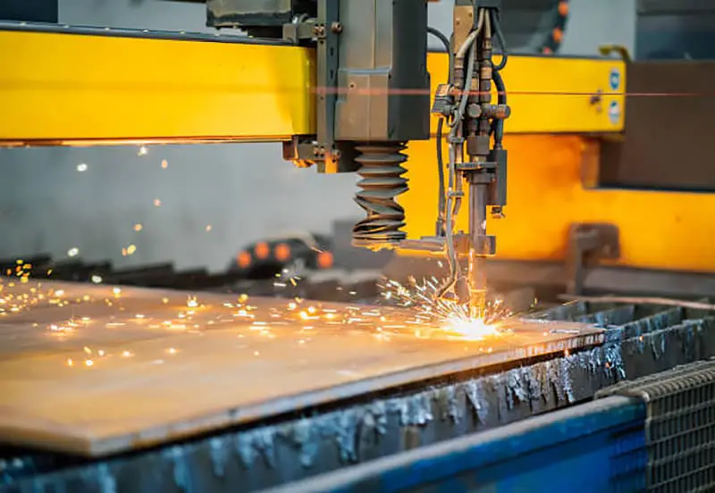
3. CNC plasma cutting method
Next, the basic principle of plasma cutting and its application in shipbuilding will be mainly presented.
Plasma cutting method:
There is an essential difference between the plasma cutting process and the principle of gas cutting. It is a physical cutting process that uses the high temperature of the plasma arc to melt the metal at the cut seam and then blows it out with a high-speed flame to form a narrow gap that separates the material as the nozzle moves.
Plasma arc is also known as compressed arc, which has a relatively small conductive cross-sectional area and therefore concentrates energy more effectively.
(1) Plasma Arc Cutting Principle
1. Plasma Arc Generation
The principle of plasma arc generation is basically the same as that of the welding arc. The arc is a stable form of gas discharge, which is the phenomenon of current passing through the gas. Under normal circumstances, gas is a good insulator. With the action of external energy, some gas atoms emit electrons and transform into positive ions – ionization.
The Principle of Arc Generation.
The magnitude of external energy is represented by the ionization potential. According to the way external energy is supplied, gaseous ionization can be divided into three forms: photoionization, collision ionization and thermal ionization. The ionization of gas in the arc is mainly thermal ionization.
The degree of ionization of the gas is expressed by the degree of ionization: the ratio of the density of ions or electrons to the density of neutral particles before ionization.
A gas with a degree of ionization of less than 0.1% is called a weakly ionized gas, the properties of which are similar to those of non-ionized gas.
Properties of ionized gas.
When the degree of ionization reaches 1%, the conductivity of the gas is close to that of the fully ionized gas. The temperature and degree of ionization of the plasma arc are significantly higher than those of the ordinary welding arc, but the conductivity of the plasma arc does not change significantly.
The cross-sectional size of the plasma arc column is relatively small and its resistance is often large. The main factor that determines the degree of ionization of the gas is temperature.
Definition of Plasma
At 30,000K, almost all gases become ionized and are in a state of complete ionization. The gas in the state of complete ionization is called “plasma”.
This gas is composed entirely of charged particles, has strong conductivity and exhibits significant electromagnetic properties, but as a whole remains electrically neutral. This is considered the fourth state of matter.
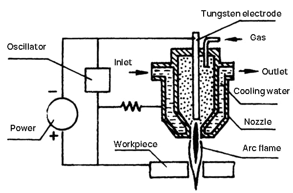
2. Principle of Plasma Arc Generating Device.
Thermal Constriction Effect (1)
The arc burns through the nozzle hole between the tungsten electrode and the metal being cut. The arc column is cooled by the cold air flow and the water-cooled nozzle orifice wall. This cooling effect causes a constriction of the plasma arc column to occur, which increases the energy density and temperature of the arc in the narrow region in the center of the plasma arc column. This phenomenon is known as the thermal constriction effect.
This effect causes the cross-sectional area of the arc column to decrease and the current density to increase.
The energy of the entire arc column is concentrated in the central region.
Thermal constriction effect (2).
This cooling effect is called the “thermal constriction effect”. With a reduced cross-sectional area, the same current requires an increased supply voltage.
At this point, the electric field intensity of the arc column increases.
The value of the electric field intensity largely reflects the degree of compression to which the arc is subjected.
Magnetic constriction effect
When the plasma arc current reaches a certain value, the magnetic field generated by the arc current further compresses the cross-sectional area of the arc column. This effect is called “magnetic constriction effect”.
Free-burning arcs also exhibit magnetic constriction effects. The plasma arc has higher current density and is based on thermal constriction, so the magnetic constriction effect is stronger.
Mechanical Constriction Effect
The opening of the nozzle orifice exerts a forced compression effect on the bow column. The flow of compressed gas or flow of water around the arc also exerts a forced compression effect on the arc column, which is known as mechanical constriction effect.
This compression of the arch is called the “mechanical constriction effect”.
Plasma Cutting Implementation
The pressure of the three constriction effects and thermal diffusion within the plasma arc reach a balance, forming a high-speed, high-temperature plasma flow that is sprayed out of the nozzle orifice.
When the plasma flow encounters low-temperature metal, it recombines into atoms or molecules and releases energy, causing the metal in the cutting seam to heat up and melt quickly. The strong mechanical force of the plasma flow pushes the molten metal to achieve cutting.
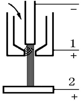
Waterjet Plasma Generating Device
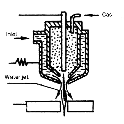
The figure illustrates a schematic diagram of a plasma generating device for waterjet cutting, which differs from conventional plasma arc cutting mainly in the nozzle structure.
Structure of Water Jet Plasma Generating Device
Add a circle of water jet holes to the arc column outlet on the nozzle. Jets of water shoot from all sides towards the arch, increasing the thermal shrinkage effect. The arch column is further reduced by water cooling.
The energy density of the arc is more concentrated, which further increases the cutting speed.
Plasma arc types:
The plasma arc generating device is formed based on the practice of tungsten electrode argon arc welding. According to the power supply connection mode, plasma arc can be divided into three types: transferred arc, non-transferred arc and hybrid arc.

Transferred Plasma Arc Generation:
The electrode is connected to the negative pole and the workpiece is connected to the positive pole. The arc is first formed between the electrode and the nozzle, and then a relatively high voltage is applied between the electrode and the workpiece. As a result, the plasma arc is transferred from the electrode to the workpiece.
Transferred Plasma Arc Applications:
The cathode point and anode point of the transferred plasma arc fall on the electrode and workpiece respectively. This results in a lot of heat generation that concentrates at the point of contact between the arc and the workpiece. This type of plasma arc can be used for both cutting and welding applications.
Since the transferred plasma arc occurs between the electrode and the workpiece, it is necessary for the workpiece to be conductive.
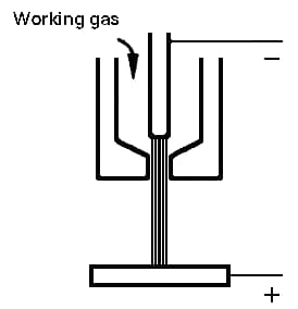
Non-Transferred Plasma Arc :
In the case of a non-transferred plasma arc, only the nozzle is connected to the positive pole. The plasma arc is generated between the electrode and the nozzle, and the high temperature flame flows through the nozzle. The anode point is at the nozzle, which causes greater heat loss and leads to a decrease in the temperature of the plasma arc.

Non-transferred plasma arc is suitable for cutting and welding thin metals and non-metallic materials.
Hybrid Plasma Arc:
Both transfer and non-transfer plasma arcs are present simultaneously. This type of plasma arc is mainly used in microarc welding and powder material spraying.
Physical characteristics of the plasma arc
(1) The thermal characteristics of the plasma arc.
Thermal characteristics are important properties of a heat source. The temperature, thermal power and thermal efficiency of the plasma arc are:
① The temperature of the plasma arc
The temperature of the plasma arc mainly refers to the temperature of the arc column. The temperature of the arc column is generally related to the arc power, gas, electrode materials and other working conditions.
The effect of gas ionization potential on temperature.
The composition of gases in space has a substantial impact on the temperature of the arc column. A higher ionization potential of the gas typically leads to a higher arc column temperature.
Furthermore, the vapor ionization potential of electrode materials can significantly affect the arc column temperature when it is lower.
When using a molten metal electrode arc, the resulting metal vapor has a low ionization potential and the temperature ranges from 5,000K to 6,000K. After plasma generation, tungsten electrodes are commonly used and do not evaporate.
The temperature of the plasma arc
The temperature of the plasma arc column can vary between 15,000K-50,000K, and there is an extremely high temperature gradient from the center to the edge. Compared to the other two types of plasma arc, the transfer plasma arc has a higher temperature.
Under the conditions of I=300A, U=250V, d=2.8mm nozzle opening and a gas flow rate of Q=50l/min, using nitrogen as the working gas, the maximum temperature close to the nozzle reaches T max. =30000℃. At I = 1500A and d = 2.5 mm, T max. =52,000 ℃, and the energy concentration reaches 1.1×10⁹ W/cm2.
② The thermal power of the plasma arc
A high temperature heat source does not necessarily mean a higher heating capacity. The heating capacity of a heat source depends on its thermal power – the amount of thermal energy it can transfer per unit of time.
The thermal power of an arc is the amount of electrical energy converted into thermal energy in a given time, also known as power consumption. This represents the amount of heat generated by the arc per unit of time.
Calculation of the thermal power of a plasma arc.

Due to its high operating voltage (V) and current (I), a plasma arc generates a significant amount of thermal energy. As a result, the thermal power of a plasma arc can be adjusted by adjusting several parameters.
Influential parameters on thermal energy
The working current of a plasma arc depends on several factors, such as the geometry and size of the nozzle, the composition and flow rate of the working gas, and the electrode material.
These parameters play a critical role in determining the operating current of a plasma arc. Furthermore, the influence of gas composition can guide the selection of the working gas.
When used as a heat source, a plasma arc generates a substantial amount of heat. The gas plays a crucial role in transmitting a significant proportion of this heat to the workpiece.
The working gas of a plasma arc
During the heating, decomposition and ionization processes that occur within the arc column, the gas absorbs heat and reaches extremely high temperatures.
The amount of heat absorbed by the gas increases as it undergoes thermal decomposition and ionization or experiences an increase in temperature, which ultimately increases its heat transfer capacity.
From the point of view of thermal decomposition, only gases in a molecular state can be subject to this process. Working gases for plasma arcs include H2, N2, air, water vapor, argon and others.
As the temperature of the gas used in plasma arc combustion increases, its enthalpy also increases.
The thermal efficiency of a plasma arc
Electrical energy is transformed into thermal energy in the plasma gun, but not all of it is used to heat the part. Some is removed by water cooling and radiation. With the transferred arc, there is less heat loss and the part can receive 60% of the thermal energy.
The actual amount of thermal energy received by the part is the effective thermal power of the plasma arc.

(2) Plasma arc flame speed
The flame speed of the plasma arc is extremely fast, reaching supersonic speeds of up to 300-1000m/s and has strong blowing force. The gas in the part is rapidly expanded due to heating in the nozzle channel, resulting in a fast jet velocity due to thermal acceleration.
In cutting processes, plasma arcs with fast flame speeds and high impact forces are known as rigid arcs. Small-aperture nozzles and large-flow working gases are easy to obtain rigid arcs.
(3) The electrical characteristics of the plasma arc
The static volt-ampere characteristics of the plasma arc, also known as the static characteristic.
The static characteristics of the plasma arc
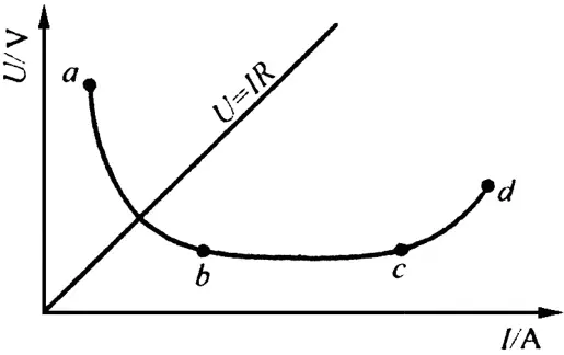
The nozzle limits the increase in the cross-sectional area of the plasma arc column. The difference between the static characteristics of the plasma arc and those of an ordinary electric arc manifests itself in two aspects: a higher voltage and a tendency to exhibit a flat or rising characteristic.
The static characteristics of the plasma arc are related to the type and flow of the working gas, nozzle size, electrode spacing and other factors.
(4) The combustion stability of the plasma arc.
When using a transferred arc plasma, a phenomenon called double arc may occur, which may disturb the stability of plasma arc combustion.

The double arc may disrupt the normal progress of the cutting process and cause damage to the nozzle.
Double arc phenomenon
Under certain current and external conditions, the arc voltage always tends to maintain a minimum value. This is an important rule in arc physics known as the minimum voltage principle.
When a double arc occurs, the voltage of A1+A2 is lower than that of the plasma arc, therefore, the voltage drop in the nozzle channel is directly related to the double arc phenomenon.
Double arc and plasma arc voltage
To increase the degree of arc compression, it is desirable to reduce the nozzle opening and lengthen the plasma arc, thus increasing the tension and the magnetic contraction effect.
The voltage is directly proportional to the arc length, therefore excessive increases in arc length should be limited from the perspective of preventing the double arc phenomenon. There are also other factors that can affect the double arc phenomenon.
(2) Plasma arc cutting equipment and process
1. Plasma arc power supply.
The relationship between the output current and the voltage at the power supply terminals is known as the external characteristics of the power supply.
Plasma arc requires the power supply to have an external steep drop characteristic.
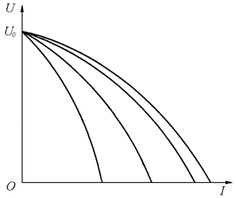
The open circuit voltage (U 0 ) of the power supply.
To facilitate the ignition and stable combustion of the plasma arc, the U0 requirement for the power supply is relatively high.
For welding, thermal spraying and other processes, U0 > 80V is sufficient, while cutting and spraying require U0 > 180V. The magnitude of the open circuit voltage depends mainly on the thickness of the material to be cut, with thicker materials requiring higher U0.
The power supply for plasma arc cutting
The commonly used power supply for plasma arc cutting is mainly a DC arc welding power supply with external sharp drop characteristics, and there are specific models available. Sometimes AC power supplies are used for certain processes or materials, which is common in plasma arc welding.
In some cases, general-purpose arc welding machines can be used by connecting several welding machines with the same current type and external characteristics in series.
The open circuit voltage of domestically produced plasma cutting machines is generally 120V-300V, with a working current of 320A-500A and a working voltage of 60V-150V.
2. Plasma arc electrode material
The electrode materials for the back electrode are the same as those for TIG welding, including tungsten electrodes, thoriated tungsten electrodes and ceriated tungsten electrodes.
Pure tungsten with a melting point of 3400 ℃ and a boiling point of 5000 ℃ can generally meet the requirements, but it must be well cooled to reduce wear. Adding 1-2% thorium oxide to pure tungsten produces thoriated tungsten electrodes, which have greater electron emission capacity than pure tungsten electrodes.
Under the same electrode diameter conditions, thoriated tungsten electrodes can be used at higher currents with slower burning rates.
Ceriated tungsten electrodes and zirconium electrodes.
Thoriated tungsten electrodes are radioactive and can be harmful to health. Ceriated tungsten electrodes are produced by adding 2% cerium to pure tungsten, which can reduce radioactive contamination and at the same time further improve electron emission capacity and process performance.
This is a more ideal choice for back electrode material as it reduces electrode burnout rates. Zirconia electrodes can use air as the working gas and have a service life close to that of thoriated tungsten electrodes when working in N2+H2 mixed gas.
3. Plasma arc working gas.
The working gases commonly used for plasma arc cutting are nitrogen (N2), argon (Ar), hydrogen (H2) or mixtures thereof. N2 has a relatively high enthalpy, stable chemical properties, low risk and low cost, making it a widely used working gas.
Nitrogen can dissolve in steel to form iron nitride, which increases strength but decreases ductility. Nitrogen purity should not be less than 99.5%. If there is too much O2 or water in the gas, it can cause severe burning of the tungsten electrode.
Working gas – Argon
Argon has a lower enthalpy and consequently the plasma arc voltage is also low. As it is a monatomic gas, argon does not decompose or have a heat-absorbing effect at high temperatures.
Its specific heat capacity and thermal conductivity are small, resulting in minimal energy loss when burning the arc in argon gas.
However, due to the high ionization potential of argon, both the arc and combustion require greater energy. Special arc forming measures must be taken to solve the difficult combustion problem.
Argon is an inert gas that does not react with or dissolve in many metals. For cutting chemically active metals, high purity argon gas is a good shielding medium.
Argon gas is heavier than air and occurs naturally in concentrations of about 1% in the atmosphere, but extracting it can be expensive. Generally, argon is a byproduct of oxygen production, and domestically produced industrial-grade argon has already reached 99.99% purity.
Hydrogen (H2) is the gas with the highest enthalpy and thermal conductivity and has the greatest capacity to transfer thermal energy.
Mixing hydrogen into the working gas can significantly increase the thermal power of the plasma arc, making it a common choice for spraying difficult-to-melt materials or cutting thick parts.
For most metal materials, hydrogen is a reducing gas that can effectively prevent the oxidation of the material.
Working gas – Hydrogen, Air
Hydrogen is a combustible gas that can easily ignite and explode when mixed with air.
Hydrogen can dissolve in many molten metals at high temperatures, which can sometimes affect process performance, and hydrogen that penetrates steel can easily cause hydrogen embrittlement.
Air has a high capacity to transfer thermal energy as a working gas and is relatively cheap and convenient to use by compressing it.
Working gas – Mixed gases
In addition to using air for zirconium electrodes, tungsten electrodes can also use air as the working gas.
When using air with tungsten electrode, a double-layer airflow plasma gun must be used, and the inner layer must use gases such as argon or nitrogen to protect the tungsten electrode from oxidation by air.
Commonly used mixed gases are nitrogen-hydrogen and argon-hydrogen, which combine the advantages of both gases.
Considerations for mixed gases
Mixing proportion:
The proportion of mixed gases used can significantly affect cutting speed, cut quality and nozzle life.
For hydrogen-argon mixture, the recommended ratio is (20-40)% H2 to (80-60)% Air, while for hydrogen-nitrogen mixture, the recommended ratio is (10-25)% H2 to (90-75) ) % N2.
Arc Startup Problem:
Starting arcs in mixtures containing a large amount of diatomic gas can be difficult. However, it is usually possible to start an arc with pure argon or pure nitrogen gas.
4. Plasma arc cutting process.
Plasma arc cutting process parameters include:
- No-load voltage (U0)
- Cutting current (I)
- Operating voltage (U)
- Gas flow rate (Q)
- Cutting speed (v)
- Distance between nozzle and workpiece (h)
- Distance between tungsten electrode and nozzle tip (l)
- Nozzle hole diameter (d)
(1) No-load voltage (U0)
To ignite and maintain a stable plasma arc, a minimum no-load voltage of 150V is recommended. When cutting thicker materials (above 200 mm), a higher no-load voltage of more than 200 V is required.
For cutting very thick materials, the no-load voltage can reach 300-400V. High no-load voltage can increase the risk of electric shock, so it is important to take appropriate safety measures when working with plasma cutting equipment.
(2) Cutting current (I) and operating voltage (U)
The cutting current and operating voltage determine the power of the plasma arc. Increasing the cutting current and operating voltage can increase the thermal power of the plasma arc, allowing for higher cutting speeds and greater efficiency when cutting thicker materials.
As the cutting current increases, the cutting speed can also increase significantly. However, the effect of increasing cutting current on cutting speed becomes less significant as the thickness of the material to be cut increases.
Effective ways to increase potency:
Increasing the current will cause the arc column to thicken, resulting in a wider cut and easier burning of the tungsten electrode nozzle. Increasing voltage is an effective way to increase plasma arc power, especially when cutting thick materials. The working voltage U is related to the gas composition and flow rate. OU for N2 is higher than that for Ar. H2 requires higher U due to its strong heat dissipation ability.
Plasma arc working voltage
When U > 0.65U0, the plasma arc will exhibit an unstable phenomenon known as double arc. When increasing the working voltage of the plasma arc, it is also necessary to increase the no-load voltage of the power supply. U is also related to the geometric shape of the beak, especially the beak opening d.
Gas flow rate Q
When other conditions are equal, an increase in Q will increase the thermal contraction effect of the arc column, resulting in more concentrated energy. As Q increases, U increases, leading to an increase in plasma arc power, arc column temperature, and speed v.
At the same time, the arc jet speed increases, the cutting force is increased, and the cutting quality is also improved.
However, if Q is too large, some of the energy will be removed by cold air, resulting in a decrease in the amount of heat available to melt the metal, which may affect the stability of arc combustion and normal cutting.
(4) Cutting speed v
An appropriate cutting speed v can improve the cutting surface quality.
When power is constant, increasing v will decrease the heated area of the part and the size of the heat-affected zone.
If v is too high, the material being cut may not melt. If v is too slow, productivity will decrease, the cutting surface will become rough, burrs will increase at the bottom, and the workpiece will deform more significantly.
As long as the cutting quality is guaranteed, the cutting speed v should be increased as much as possible.
(5) Distance from nozzle to workpiece h
To fully utilize the heat generated by the plasma arc and facilitate its operation, the distance h between the nozzle and the workpiece surface must be controlled within 10 mm. Typically this distance is set to 4-7 mm.

The impact of h on the plasma arc
Increasing h is equivalent to increasing the arc length, which leads to an increase in U.
However, as the arc length increases, the efficiency decreases and the thermal radiation energy increases, which can cause a decrease in v. If h is too high, the blowing force and cutting capacity will decrease, leading to an increase in lower burrs and the possibility of doubling. bow. If h is too small, there is an increased risk of a short circuit.
(6) Nozzle parameters – l, d
l refers to the distance between the end of the tungsten electrode and the end of the nozzle, which is related to whether the arc can be compressed properly.
If l is too large, it will destroy the stability of the arc. If l is too small, it may cause a short circuit between the tungsten electrode and the nozzle, which may burn the nozzle.
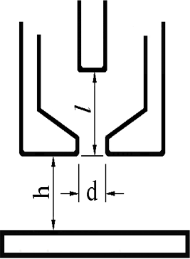
The nozzle diameter d affects the diameter and temperature of the arc column. An increase in d will result in a decrease in compression, energy density, cutting force and cutting speed v. This can also cause a decrease in cutting capacity.
In general, smaller d is associated with larger U, while larger d is associated with smaller U.
5. Features of cutting thick parts.
As the thickness t increases, the amount of melted material also increases, which requires an increase in power.
To reduce depletion, it is recommended to increase U while maintaining constant power. As t increases, the range of anode point jumps also increases and therefore U must be greater than 220 V to ensure arc stability. Sufficient heat is required to cut the bottom, resulting in a thin, elongated arc with a small axial temperature gradient.
Working gas with high enthalpy and thermal conductivity, such as N2+H2, is recommended.
Laser cutting method
(1) Introduction to the principle of laser cutting
The horizontal laser beam emitted by the laser cutter.
After being reflected by a 45-degree mirror, the laser beam is redirected vertically downwards.
The laser beam is then focused by a lens, creating an extremely small spot at the focal point.
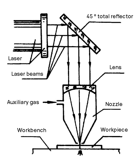
Laser cut
The power density of the spot reaches 10 6 -10 9 C/cm 2 . When the workpiece is irradiated by the laser spot, it generates a localized high temperature (above 10,000℃), causing the workpiece to melt or vaporize instantly. As the cutting nozzle moves, a cut is formed in the workpiece.
Meanwhile, an auxiliary gas with a certain pressure is used to blow the molten slag into the cutting, thereby cutting the workpiece.
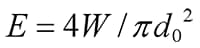
Laser power
The laser beam is an ideal parallel beam (with divergence angle θ <0.001 radians). After focusing, the spot diameter can be represented by d ó = f θ (where θ ≠ 0), where f is the focal length of the lens. If the laser power is W, then the point power density is:
Features of laser cutting
Compared to gas cutting and plasma arc cutting, laser cutting has the following advantages:
- Faster cutting speed
- Narrower cutting width (about 0.2-0.3mm)
- Smaller heat-affected zone (with a width of about 0.1 mm)
- Better perpendicularity at the cutting edge
- Higher surface finish quality of the cutting edge
Laser cutting applications
Laser cutting has remarkable advantages in cutting thin sheets, improving cutting efficiency and reducing thermal deformation.
It can cut various high-melting point materials, heat-resistant alloys and super-hard materials, as well as semiconductors, non-metallic materials and composite materials.
When cutting thick metals, compressed gas is blown to aid the cut, reducing the width of the cut and the heat-affected zone.
(2) Practical applications of laser cutting
The application of laser cutting technology dates back to the 1970s. Currently, the US Navy is a leader in the use of laser technology for shipbuilding research. In the last years,
Japan has produced and sold CNC laser cutting machines with power below 5 kW, which can cut low-carbon steel up to 32 mm thick with high quality. When cutting a 12mm board, the cutting speed is about 2.5m/min, which is comparable to existing plasma arc cutting machines.
Laser cutting has many applications on shipyards, including:
Mitsui Zosen Corporation's Tamano Shipyard mainly builds warships and also 40,000-ton bulk carriers. Most sheet thicknesses for ship components are around 10 mm and a significant proportion of thin steel sheet processing is required. Ship structures require low thermal deformation and high cutting precision due to the relatively thin structure of the steel plates used. The use of laser cutting machines in the production of steel sheets for ship bodies has achieved significant results.
Yunao Shipyard Laser Cutting Machine
The Japanese-made CO2 laser cutting machine for aircraft, with a gauge of 7.5 m, has a maximum power of 3.5 kW (rated power of 3 kW). It has an effective cutting width of 5.4 m, effective cutting length of 29.1 m and can cut up to a maximum thickness of 19 mm. The cutting speed for sheets with a thickness of 8-10 mm is between 900-1000 mm/min. The incision width is less than 0.5 mm and the cut deformation is minimal. There is no top edge collapse or bottom edge dross, and the cutting accuracy is much higher than plasma arc cutting.