There is both bending moment and shear force in the cross section of a beam subjected to transverse force, resulting in normal stress and shear stress in the cross section. The bending shear stress of several common beam sections will be discussed below.
Rectangular section
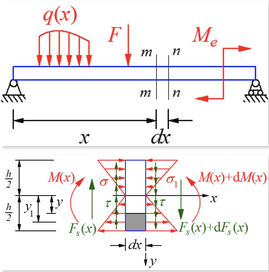
A small segment of length dx is cut from the beam under bending by transverse force. The beam is unloaded and the shear forces on both sides of the segment are equal but in opposite directions. The bending moment in the right section is greater than that in the left section, resulting in different normal stresses in the two sections.
For a narrow rectangular section, the shear stress is tangent to the boundary on both sides of the beam due to the absence of shear stress on the side. This means that because the beam is symmetrically bent and parallel to the boundary, the shear stress in the y-axis of the symmetry axis must be in the y-direction and changes little along the width direction.
Therefore, the following assumptions are made about the law of distribution of shear stress in the cross section:
- The direction of the shear stress at each point in the cross section is parallel to the shear force;
- The shear stress is evenly distributed across the width of the section, that is, the shear stress at each point on the horizontal line parallel to the neutral axis is equal.
When the height-to-width ratio of the section is greater than 2, the solution based on the above assumption is sufficiently accurate compared to the exact solution from elastic theory.
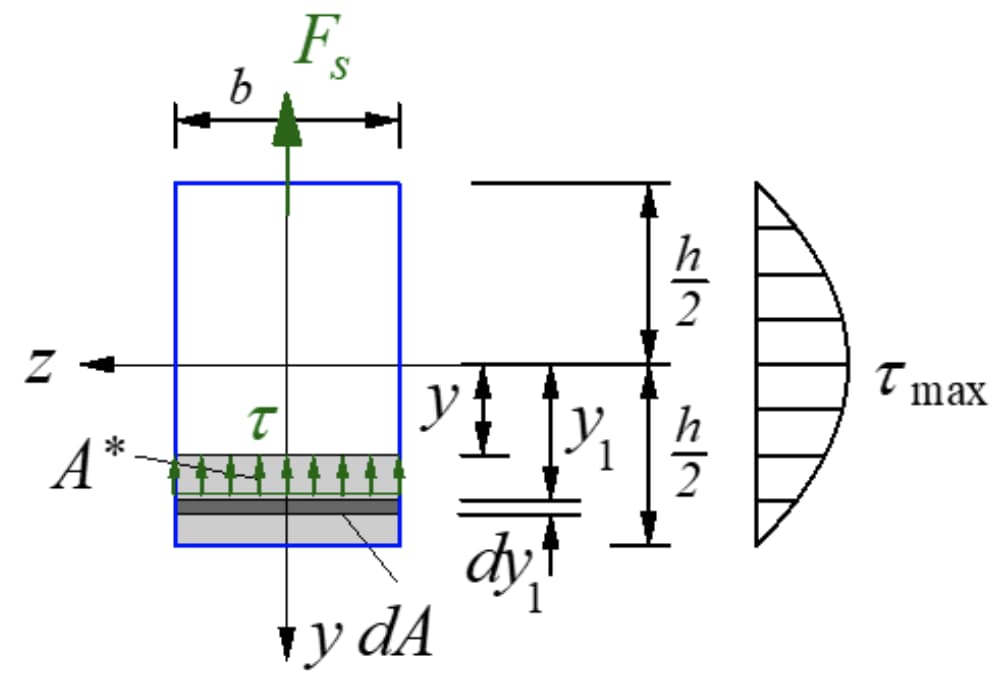
According to the shear stress reciprocity theorem, there must be a shear stress equal to the size of the cross section in the longitudinal section perpendicular to the cross section. Cut a microsegment along the longitudinal plane with the neutral moment axis away from y and take the microelement on the lower side of the longitudinal plane. The forces are shown in the figure below.

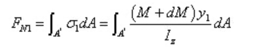
The force resulting from the normal tension in the left section is:
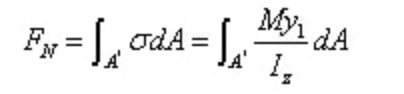
The force resulting from the normal tension in the right section is:
It is clear that the two resulting ones are of different sizes. There must be a force along the axial direction in the longitudinal section to maintain the balance of the microsegment. This force is the result of shear stress, confirming the presence of shear stress in the longitudinal section.
Since dx is a small quantity, let the shear stress in the longitudinal plane be distributed evenly:
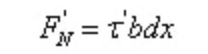
According to equilibrium conditions:
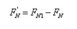
That is,
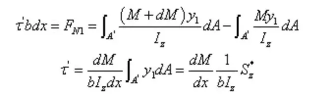
In between,
From the reciprocal shear stress theorem and the differential relationship between shear force and bending moment:
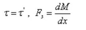
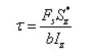
Of which:
- b is the width of the horizontal line with the neutral line of the moment y in the section, which is constant for rectangular sections;
- L z is the moment of inertia of the neutral axis of the entire cross section;
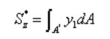
- S z* is the static moment of the area outside the horizontal line whose neutral axis is y in the cross section of the neutral axis;
- F S is the shear force in the cross section.
In between,
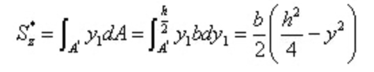
Substitute into the shear stress calculation formula
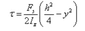
The shear stress is distributed in a parabola along the height of the section.
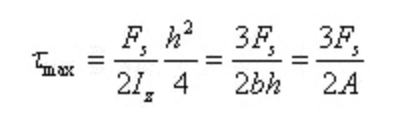
When y=0, there is maximum shear stress in the section on the neutral axis
The angular deformation is
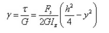
It can be seen that the angular deformation is also distributed parabola along the height of the section.
At this time, the bending shape of the cross section when the cross force doubles is shown in the figure below, which verifies that the bending deformation of the cross force does not meet the plane assumption.
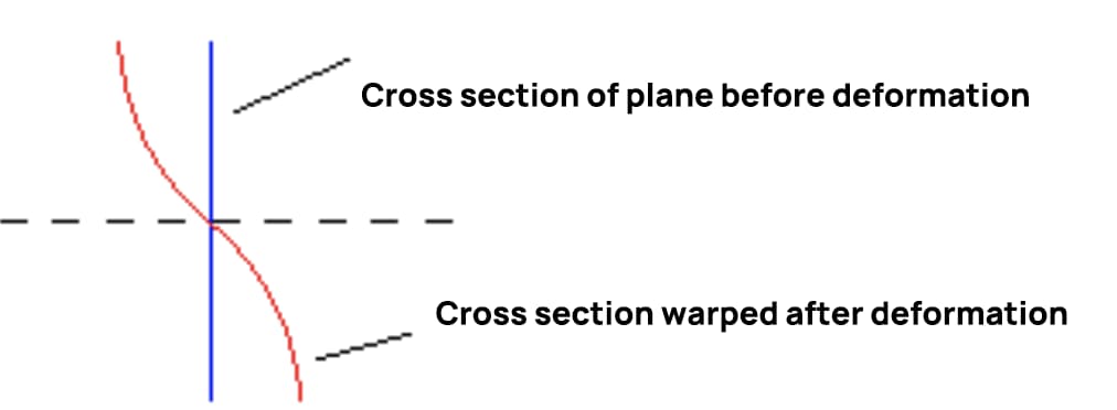
When the shear force remains constant, the shear stress in consecutive cross sections is equal and the degree of warping is also equal. The length of the longitudinal fibers does not change due to warping of the section, so additional normal stress will not result. If the shear force changes with the section position, the degree of warping in two consecutive sections will be different, leading to additional normal stress in the section.
For symmetric sections of other shapes, the approximate shear stress solution can be derived using the above method.
For a rectangular section, in the stress calculation formula, the section width (b) is constant, and the static moment of half the cross-sectional area of one side from the neutral axis to the neutral axis is the largest. As a result, the shear stress at each point on the neutral axis is greater.
For symmetric sections of other shapes, the maximum shear stress in the cross section is normally located at various points on the neutral axis, with the exception of sections with significantly increased width on the neutral axis (such as cross sections) or some sections with varying width (such as cross sections). of isosceles triangle).
Therefore, for I-shaped, annular and circular section beams, the maximum shear stress at each point on the neutral axis will be mainly discussed below.
C circular section
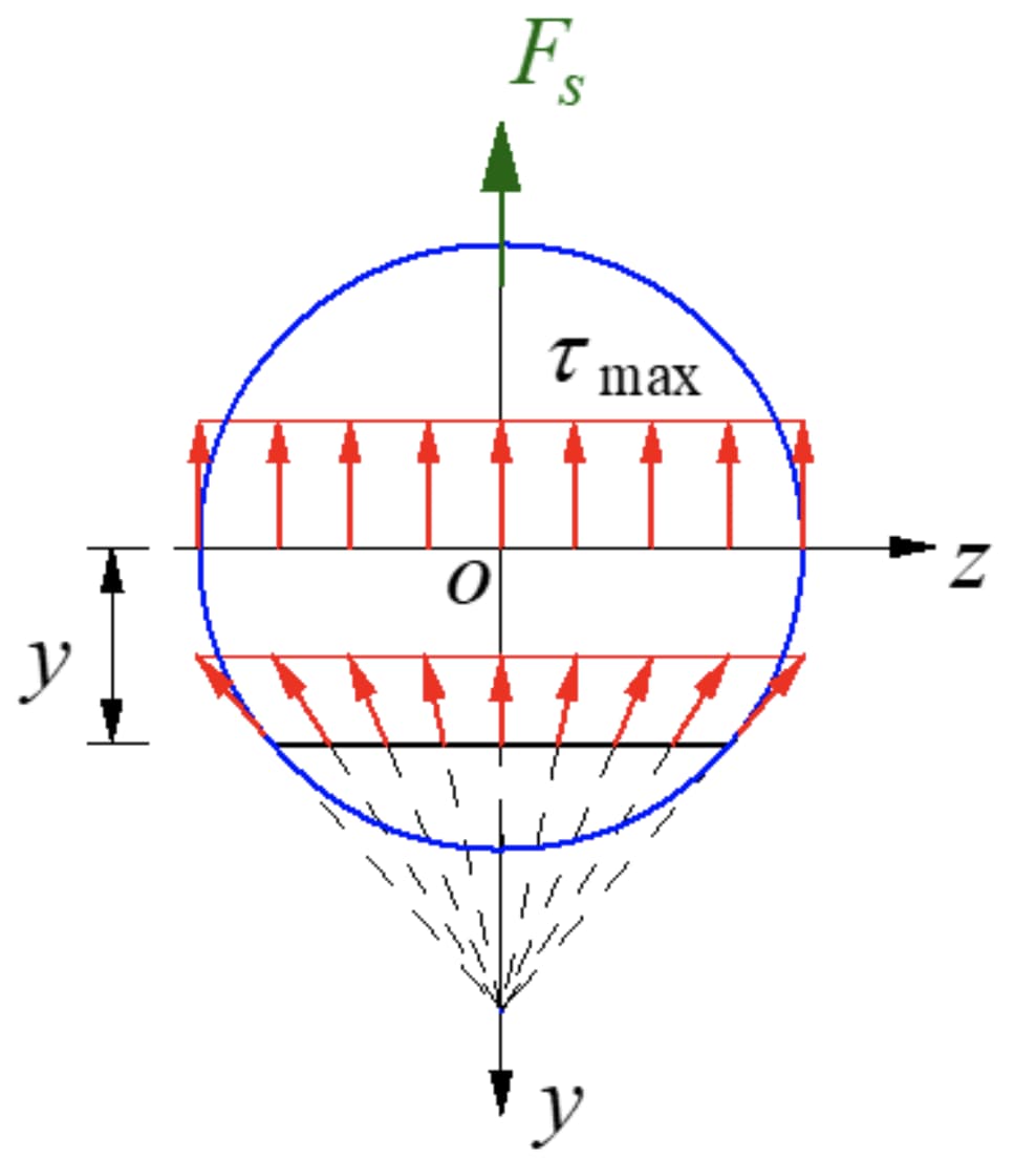
The shear stress at each point on the edge of a circular section is tangent to the circumference, according to the reciprocal shear stress theorem. At each point on the axis of symmetry, the shear stress must be in the y direction. It can be assumed that the shear stress distribution converges at a point on the axis of symmetry for each point along the y-width of the neutral axis, and the shear stress components along the Y-direction at each point along the width they are the same.
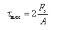
The maximum shear stress of the circular section is still on the neutral axis, and its direction is parallel to the external force, with the same value at each point on the neutral axis.
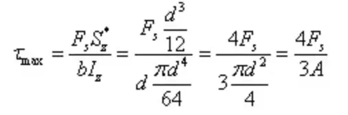
The maximum shear stress is
I-shaped cross section
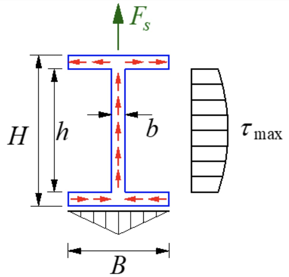
The I-shaped section is a thin-walled open section with a stress distribution as shown in the figure. The magnitude of shear stress across the wall thickness is equal, known as shear stress flux, flowing in the direction of shear.
The component of shear stress parallel to the y-axis in the flange is secondary and insignificant, with the main focus being on the component parallel to the long side of the flange. The shear stress in the web has a parabolic distribution, with its size shown in the figure.
The maximum shear stress is at the neutral axis.
In the case of I-shaped steel, the maximum shear stress:
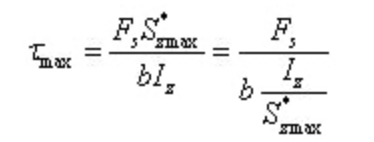
Where, b is the thickness of the web, and i z /s* zmax can be obtained by referring to the steel profile table.
If it is an I-shaped section made up of three long, narrow rectangles, the maximum and minimum shear stresses in the web can be obtained as follows:

From the above two formulas, it can be seen that the width of the web is much smaller than the width of the flange, so the maximum shear stress in the web is not much different from the minimum shear stress.
Therefore, it can be considered that the shear stress in the web is approximately uniformly distributed.
The resulting shear stress in the web accounts for 95-97% of the total shear force, and the shear force in the cross section is mainly borne by the web.
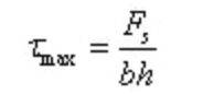
Since the web bears almost all of the shear force in the section, and the shear stress in the web is almost uniformly distributed, the maximum shear stress can be roughly calculated by dividing the shear force by the cross-sectional area of the ventral pole:
At the same time, the entire area of the I-beam flange is farthest from the neutral axis, and the normal stress at each point is relatively large, so that the flange bears most of the bending moment in the section.
Thin-walled annular section
The thickness of the thin-walled annular section is d, the mean radius of the ring is r and the thickness is much smaller than the mean radius, therefore it can be assumed that:
The shear stress in the cross section is equal throughout the wall thickness;
The direction of shear stress is tangent to the centerline of the section, and the direction of shear stress flow is along the shear direction.
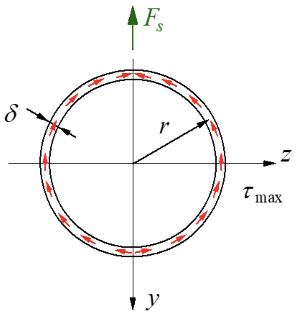
The maximum shear stress is located at the neutral axis:
Where, A is the area of the annular section.
Beam strength condition
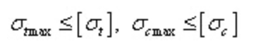
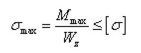
Bending normal stress strength condition:
For neutral axisymmetric sections, the maximum tensile normal stress and maximum compressive normal stress are equal.
Plastic materials are commonly used and their strength conditions:
For the section with an asymmetric neutral axis, the maximum normal tensile stress and the maximum normal compressive stress are not equal.
Brittle materials are commonly used and their strength conditions:
The flexural shear stress resistance condition is:
Measures to improve the flexural strength of beams
Normal bending stress is the main factor controlling the beam.
Therefore, the bending normal stress strength condition is often the main basis for beam design.
From the strength condition, to improve the beam's strength capacity, two aspects must be considered:
On the one hand, the beam tension should be reasonably arranged to reduce the maximum bending moment;
On the other hand, a reasonable section shape is adopted to improve the section bending section coefficient and make full use of the material properties.
1. Arrange beam tension reasonably
Improve the tension condition of the beam and try to reduce the maximum bending moment in the beam.
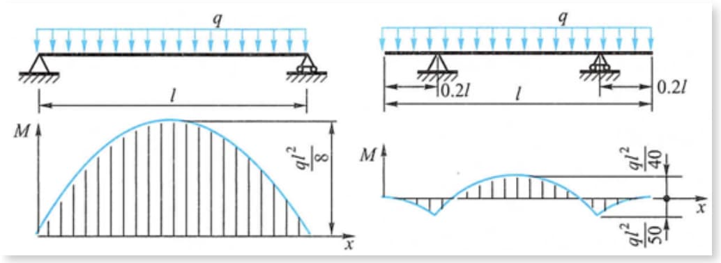
As shown in the figure, the maximum bending moment in the beam under uniform load is greatly reduced when the support is moved inward by a certain distance from the positions of both ends of the beam.
For example, the beam and cylindrical container of the gantry crane, whose fulcrum moves slightly towards the middle, can achieve the effect of reducing the maximum bending moment.
2. Reasonable beam section
The higher the bending section coefficient, the lower the stress and the higher the load capacity of the beam.
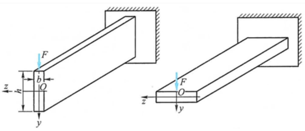
For example, when the beam is loaded in the vertical direction, the bending section coefficient is larger when the section is placed vertically, so it is more reasonable to place it vertically than horizontally.
By improving the section's bending coefficient, we also hope to use fewer materials to achieve better economy.
Therefore, the ratio of the bending section coefficient to the section area is generally used to measure the rationality of section design.
Under the same cross-sectional area, the rectangular section (height greater than the width) is more reasonable than the circular section, while the I-shaped section or box section is more reasonable than the rectangular section.
Therefore, to make the most of the materials, the materials should be placed as far away from the neutral axis as possible.
When discussing the reasonable shape of the section, the mechanical properties of the material should also be taken into consideration.
Materials with the same tensile and compressive strength (such as low-carbon steel) should adopt neutral axisymmetric sections, such as circular, rectangular, I-shaped, box, etc.
In this way, the maximum tensile stress and the maximum compressive stress at the upper and lower edges of the section can be equal.
For materials with unequal tensile and compressive strengths (such as cast iron, cement, etc.), the section shape with neutral axis inclined towards the tension side must be adopted.
Equal resistance beam concept
The beams discussed above are all of equal section and the bending section coefficient is constant, but generally, the bending moment of each beam section changes with the position of the section.
The design of the equal straight beam section should be carried out according to the maximum bending moment, and its maximum stress is close to the allowable stress.
The bending moment in other sections is small, so the stress is small and the material is not fully utilized.
To save materials and reduce self-weight, the section size can be changed so that the bending section coefficient changes with the bending moment.
A larger section is used where the bending moment is greater, while a smaller section is used where the bending moment is smaller.
This type of beam whose section changes along the axis is called a variable section beam.
If the maximum normal stress in each cross section of a beam of variable cross section is equal and equal to the allowable stress, it is called an equal strength beam.