1. Transmission principle of mechanical shear machine
As depicted in Figure 1, the motor turns the large pulley through the use of a small pulley. The large pulley, in turn, causes the large and small gears to rotate through the drive shaft. The large gear drives the rotation of the eccentric wheel through the main shaft.
Finally, the eccentric wheel moves the slider (upper tool holder) up and down, resulting in shear, through the connecting rod.
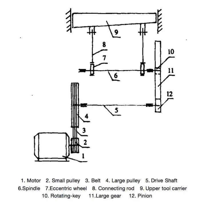
Fig. 1 Schematic diagram of cutting machine transmission principle
2. Analysis and troubleshooting of mechanical cutting machine
2.1 The width of the shear parts is not consistent, and the repeat accuracy of the batch parts is out of tolerance.
Cause analysis:
- Incorrect positioning of the baffle plate and the large gap between it and the shear blade are causing movement during locking.
- The movement of the baffle plate is not synchronized on both sides, resulting in a large gap between the transmission parts.
- Improper adjustment of the pressure spring force leads to uneven pressure and movement of the plate material during shearing.
- Deformation of the baffle plate and out-of-tolerance straightness are causing inaccurate positioning of parts.
- The clearance between the upper and lower movable guide rail of the shear blade slider and the pressure plate is not adjusted correctly.
Elimination method:
- The gap must be eliminated to make the distance between the baffle plate and the shear blade consistent. The repeated positioning error must be within 0.03/1000 after locking.
- The gap between the transmission parts must be eliminated.
- The gap between the pressure beam and the metal sheet should be adjusted to approximately 10mm, and the spring compression force should be adjusted to 11kn and kept uniform at both ends.
- The flatness and straightness error of the baffle plate must be repaired to be within 0.02/1000.
- The gap between the guide rail and the pressure plate should be adjusted to 0.03 mm.
2.2 The surface straightness of the shear parts is out of tolerance, with convex or concave phenomenon.
Cause analysis:
- The large horizontal error in installing the work table is causing distortions in the equipment.
- The large flatness error of the vertical supporting surface of the upper and lower shears is causing the straightness of the shear blade to exceed the tolerance after clamping.
- Movement of the shear blade up and down, twisting of both sides of the guide rail surface (not in the same plane), or wear of the guide rail are causing the straightness to be out of tolerance.
Elimination method:
- Realign the equipment installation level to ensure an accuracy of 0.05/1000.
- Correct the adjustment support surface of the upper and lower shear blades and ensure a levelness of 0.03/1000.
- Repair and scrape the bed guide rail to ensure that both ends are parallel to each other and the straightness is guaranteed within 0.02/1000.
2.3 The burr on the cutting part of the part is very large.
Cause analysis:
- The gap between the upper and lower shear blades is not adjusted correctly.
- The tip became worn and dull.
- The gap between the upper and lower shear blades is uneven, resulting in burrs appearing in the larger gap.
Elimination method:
- Adjust the gap to be between 5% and 8% of the sheet thickness.
- Replace or sharpen the cutting edge.
- Adjust and inspect every 500mm to ensure the gap is uniform and does not exceed 0.05mm.
2.4 The narrow strip is cut and the pieces are twisted and deformed.
Cause analysis:
- The surface clearance of the cutting blade slide guide is too large.
- Both sides of the cutting blade slider guide surface are twisted or out of tolerance due to wear.
Elimination method:
- Adjust the pressure plate to ensure that the guide rail clearance on both sides is within 0.03 mm.
- Scrape the slide block and bed guide rail so that the contact surface of the slide block and bed guide rail is (25 x 25) mm 2 with 12 points, and the straightness is within 0.02/ 1000.
2.5 There are historical materials and pushing materials in the narrow shear parts
Cause analysis:
- The plane of the deflector plate is inclined and not perpendicular to the horizontal plane.
- The parallelism of the mounted vertical support surface with the upper blade is out of tolerance.
Elimination method:
- Repair the plane of the baffle plate to ensure it is perpendicular to the horizontal plane.
- When the upper turret moves down, adjust the distance between the two vertical surfaces that fit the upper blade and the lower blade to ensure an error of 0.02/1000.
2.6 Single stroke clutch does not engage and shear blade does not engage.
Cause analysis:
- Wear on the rotating part of the rotary switch and the triangular notch on the damper bushing causes the clutch to slip when engaging the crankshaft.
- The rotary switch control spring is broken or loose, causing insufficient force and lack of flexibility in the movement of the rotary switch.
- The brake band and brake disc are adjusted too tightly, resulting in clutch slippage.
Elimination method:
- Replace the rotary switch and repair the triangular notch on the damper sleeve to ensure that the rotary switch moves freely and the combination is secure when the triangular notch is engaged.
- Replace the spring and adjust the tension to ensure the rotary switch moves freely.
- Adjust the tightness of the brake band.
2.7 Continuous cutting occurs during a single stroke.
Cause analysis:
- The pin head and rotary switch lever control block are worn, causing the rotary switch pin head to not lock into place.
- Incorrect control board position adjustment is preventing the rotary switch pin head from locking into place.
Elimination method:
- Repair the pinhead of the rotary switch by soldering it and restoring it to its original design size.
- Adjust the mutual position of the control block and repair it.
2.8 There is an abnormal impulse and noise phenomenon in a shear slider movement.
Cause analysis:
- The rotary switch does not fit properly into the triangular groove of the damper bushing, causing wear and improper rotation angle of the rotary switch. This results in impact and noise during the reciprocating movement of the cutting edge.
- The spring force of the rotary switch is too weak to hold it in place, causing impact when the slider moves from top to bottom.
- The balance spring force for the up and down movement of the cutting blade slider is not adjusted correctly.
Elimination method:
- Repair the contact surface between the rotating part of the rotary switch and the triangular groove of the buffer sleeve to ensure that the switch rotates freely and reliably.
- Adjust or replace spring to provide sufficient force.
- Adjust the spring force until the slider moves smoothly without shock or vibration.
2.9 When the steering wheel is idling, the clutch makes a rhythmic sound.
Cause analysis:
- The rotating part of the rotary switch does not fully disengage from the triangular groove of the damper bushing, resulting in a sound after one rotation.
Elimination method:
- Sand the contact surface of the rotary switch and adjust its position to solve the problem.