1. Concept of fatigue and fracture
- Fatigue: Fatigue refers to the change in performance of metallic materials when subjected to repeated stress or deformation.
- Fatigue Fracture: When a material is subjected to alternating cyclic stresses or strains, the gradual development of internal defects and local structural changes can cause a decline in its mechanical properties, ultimately leading to a complete fracture of the product or material. This process is known as fatigue fracture or metal fatigue.
It is important to note that the stress that causes fatigue fracture is generally of low magnitude. Furthermore, fatigue fracture is often characterized by its sudden, highly localized nature and sensitivity to various defects.
2. Classification of fatigue fracture
1. High cycle fatigue and low cycle fatigue
High cycle fatigue refers to fatigue that occurs when the level of stress acting on parts or components is low and the number of failure cycles is greater than 100,000. Examples of products that typically experience high cycle fatigue include springs, drive shafts, and fasteners.
On the other hand, Low Cycle Fatigue refers to fatigue with a high level of stress and a low number of failure cycles, generally less than 10,000 times. An example of low cycle fatigue is fatigue damage to pressure vessels and turbine parts.
2. Stress and strain analysis
Creep fatigue refers to low-cycle fatigue with high stress and short cycle times.
On the other hand, stress fatigue is characterized by low stress and high cycle times and is known as high cycle fatigue.
In practice, it can often be challenging to differentiate between stress and exertional fatigue.
Both types can occur simultaneously, which is known as compound fatigue.
3. Classification according to the type of load
Bending fatigue, torsional fatigue, tension and compression fatigue, contact fatigue, vibration fatigue, friction fatigue.
3. Characteristics of fatigue fracture
Macroscopically, the cracking process can be divided into three stages: crack origin, propagation zone and transient fracture zone.
Crack origin refers to the area on the surface with grooves, defects, or stress concentrations that serve as a precondition for crack initiation.
The fatigue propagation zone is characterized by a relatively flat section where fatigue propagation occurs perpendicular to the stress direction, resulting in the formation of distinct fatigue arcs, also known as beach marks or shell marks.
The instantaneous fracture zone is where the fatigue crack extends rapidly to result in an instantaneous fracture. The fracture surface shows metal slide marks and, in some cases, there may be radioactive bands and areas of shear.
Microscopically, the typical feature of fatigue fracture is the appearance of fatigue striations. Additionally, cleavage and near-cleavage phenomena (terms used in crystallography to describe small planes seen in microscopic images) and microstructural features such as dimples may also be present in some microscopic samples.
4. Characteristics of fatigue fracture
(1) Fatigue fracture is characterized by the absence of obvious macroscopic plastic deformation during the fracture process, and there are usually no warning signs before fracture. This often leads to sudden and damaging failures of mechanical parts.
(2) The stress that causes fatigue fracture is generally low, often less than the tensile load required to reach the yield point under static loading conditions.
(3) After fatigue failure, it is common to see clear evidence of crack initiation, propagation, and fracture end zones on the fracture surface.
5. Case analysis
A motorcycle in a factory suffered a mechanical failure after traveling 2,000 km. After disassembly and inspection, it was discovered that the engine crankshaft connecting rod was broken.
The connecting rod, made of 20CrMnTi, was carburized on the surface. The operating principle of the connecting rod is represented in Figure 1, where its reciprocating movement drives the rotation of two drive crankshafts.
20CrMnTi is a structural steel alloy with a carbon content of approximately 0.2%, a manganese content of approximately 1%, and a titanium content of approximately 1%. This material is commonly used for shaft components and requires carburizing.
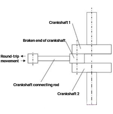
Figure 1
1. Macro inspection
The defective connecting rod had two fractures. In the bearing curvature at the fracture end of the connecting rod, many cracks parallel to the fracture are visible (Figure 3(a)). One side of the fracture end shows a strong friction trace (Figure 3 (b)), with a wear depth of 0.5 mm. Furthermore, a blue-gray high-temperature oxidation trace can be seen at one end of the bearing arc near the friction side (Figure 3(c)).
Fracture 1 is relatively smooth and flat with a worn edge, and the fatigue arc is visible in the middle (Figure 3 (d)). However, no fatigue arc was found in fracture 2.
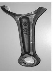
Figure 2
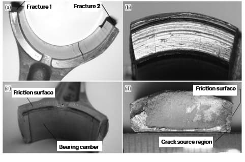
Figure 3
2. Scanning electron microscope analysis
Figure 4(a) in Fracture 1 shows a fatigue arc under a scanning electron microscope. The arc trend allows determination of the source of fatigue.
The source of fatigue is located in the upper right corner of Figure 4 (d). Local magnification reveals that most of the fine tissues in the source area have been subjected to wear, although the characteristic radial edge is still visible (Figure 4(b)).
Figure 4 (c) shows fatigue bands and secondary cracks in the fatigue growth zone.
In contrast, Fracture 2 exhibits dimpling but no fatigue stripes. It can be deduced that Fracture 1 is the primary fracture and Fracture 2 is a secondary fracture.
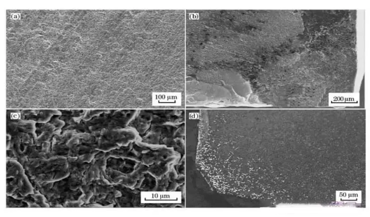
Figure 4
3. Chemical composition
Take samples from the connecting rod body and analyze its chemical composition, including mass fraction (%).
The analysis results comply with the chemical composition requirements specified in GB/T3077-1999 for 20CrMnTi.
4. Analysis of results
Based on the inspection results, the chemical composition of the material of the failed part meets the technical requirements. However, the broken end of the connecting rod has strong friction on one side.
An analysis of the end of the rolling arc close to the friction surface revealed the presence of a blue-gray oxide film, which is a mixture of black iron oxide (Fe 3 Ó 4 ) and red iron oxide (Fe 2 Ó 3 ) formed at temperatures above 400°C. This indicates that friction between the connecting rod and the output shaft has caused overheating in this area.
SEM analysis of the fracture surface shows that the source of the fatigue crack was in the corner close to the oxide film, in the high-temperature region. The combination of surface oxidation and high temperature increases the chance of cracking and creep damage.
Additionally, friction leads to a rough metal surface, which can cause surface tension concentration and increase the possibility of fatigue. The origin of fracture generally occurs at the point of maximum tensile stress.
According to the analysis of the forces acting on the connecting rod, the greatest tensile stress is present in section 1 of the fracture, making it susceptible to the formation of cracks near the corner of the friction surface. The presence of coarse carbides in this area exacerbates the problem as it disrupts the continuity of the matrix structure, accelerates the formation and propagation of cracks, reduces fatigue resistance and eventually leads to fatigue fracture.
Excess carbides on the case-hardened surface of the connecting rod are the result of an inadequate case-hardening process. The formation of coarse and blocky carbides is mainly due to the high concentration of carbon, which is more likely to occur in sharp corners of the part, significantly reducing its useful life.
To avoid the formation of coarse carbides, it is crucial to strictly control the carbon potential of the carburizing atmosphere during the carburizing process. This will help prevent excessive carbon potential, which leads to the formation of coarse carbides on the surface of the part.
5. Conclusion
The fracture of the crankshaft connecting rod is the result of fatigue fracture. The cause of the fracture is due to the strong friction suffered by the connecting rod during use, which results in local stress concentration and high temperatures, reducing the material's fatigue resistance. The presence of large, blocky carbides in the corners of the connecting rod surface further accelerated crack growth and propagation.
6. Improvement
Reducing the roughness of friction parts during the design phase can reduce stress concentration and improve the fatigue resistance of parts. This will also help reduce high temperatures caused by friction and reduce the risk of creep damage.
To improve the carburizing process, it is important to address excessive carbide formation on the carburizing surface of the connecting rod, caused by an inadequate carburizing process. Thick, blocky carbides are primarily the result of high carbon concentration, which is more likely to form in the sharp corners of the workpiece and significantly shorten its service life.
Therefore, strict control of the carbon potential of the carburizing atmosphere during the carburizing process is essential to prevent the formation of coarse carbides on the part surface due to excessive carbon potential.
6. Methods for improving the fatigue limit or fatigue strength of materials
It is often a challenge to modify the service conditions of parts, which is why it is essential to optimize the design of parts as much as possible, starting with surface effects.
By preventing the concentration of surface stresses in structural materials and mechanical parts, the accumulation of dislocation slip is hindered and plastic deformation is restricted. This makes it more difficult for fatigue cracks to form and grow, ultimately increasing the fatigue limit or fatigue strength.
1. Measures to reduce stress concentration
In design, it is advisable to avoid square or sharp corners, holes and grooves. In cases where the section size changes suddenly, such as the shoulder of a stepped shaft, it is recommended to use a transition fillet with a radius sufficient to reduce the stress concentration.
If increasing the transition fillet radius is not feasible due to structural constraints, finer grooves or counterbores may be cut into the larger diameter shaft.
There is significant stress concentration on the edge of the mating hub and the mating surface of the shaft. To improve this, a load-relieving groove can be cut into the hub and the mating part of the axle can be thickened to decrease the rigidity gap between the hub and axle, reducing the stress concentration at the edge of the mating surface.
In fillet welds, channel welding results in much better stress concentration compared to channelless welding.
Related Reading: Complete List of Welding Symbols
2. Improve surface strength
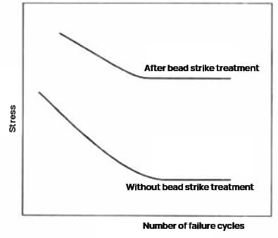
To strengthen the surface layer of components, mechanical methods such as lamination and shot peening can be used. These methods form a pre-compression stress layer on the surface of the component, reducing surface tensile stress that is prone to crack formation and improving fatigue resistance. Other methods such as heat treatment and chemical treatment such as high-frequency quenching, carburizing and nitriding can also be used.
Shot peening involves using small steel balls with a diameter of 0.1-1 mm to impact the sample surface at high speed, removing sharp corners, burrs and other stress concentrations. The surface is compressed to a depth of 1/4-1/2 the diameter of the steel ball, generating residual stress on the surface of the part and restricting the growth of fatigue cracks.
Shot peening