Large arc workpieces are a common type of steel frame sheet metal products for locomotives. Their structures are variable and the processing difficulty is greater than common parts.
In this post, we present a process method for obtaining a large radius of curvature in sheet metal parts and describe the use of the method in detail with a specific bent part. The bump bending method can also be used to make a cone on a press brake.
In the practical production of large radius parts, there are generally three forming methods:
- Integrally formed by a single-step forming die: This method is suitable for parts with complicated shapes and has the advantages of good forming effect, a smooth and flat surface of the part, no indentation and high processing efficiency. However, the cost of the mold is high and the versatility is low. It is generally used when the general process cannot be formed or the part has a high surface requirement.
- Custom punch with large radius for press brake: This type of mold is generally applicable when the part has a large radius but does not exceed the limit of the press brake table. The cost is lower than that of a single-step forming die, and the punch has a certain versatility.
- Multiple bend forming method (step bending): The basic principle is to convert the arc into a line segment, which can be formed using existing molds and equipment. Generally, undisplayed parts can be used. The application range is wide, the cost is low, no customized mold is required, and the forming quality is good.
Bending analysis of sheet metal parts with large radius
The basic principle of the multi-step forming process is to roughly divide the arc segment into polyline segments, as shown in Figure 1, to achieve the purpose of bending sheet metal with a large radius using a small radius punch.
Compared with the arc segment, the formation effect of the polyline segment is positively related to the number of polyline segments.
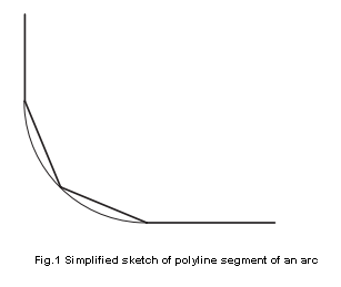
With this process method, it is difficult to avoid a prismatic structure on the part surface. However, for non-displayed parts, considering the production cycle and cost comprehensively, this process method can be used.
Application of flexural rebound
How to determine polyline segmentation and curvature angle of circular arc segments:
As shown in Figure 2, the inner radius of the bending arc of this workpiece is R350, the bending angle is 120°, and the plate thickness is 5mm.
As the use environment of the workpiece satisfies the conditions of the impact bending method mentioned above, the multi-step bend forming method is used for processing.
Based on previous experience and existing mold conditions in the workshop, the upper mold adopts R120 radius punch.
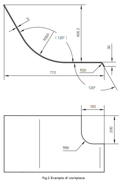
After analyzing the large arc segment of the workpiece in Figure 2, this R350 arc segment is divided into 6 polyline segments.
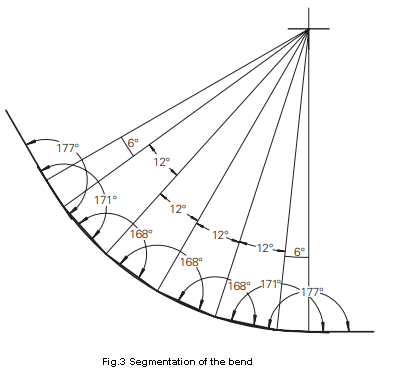
It should be noted that to ensure the smooth transition of the arc segment and the straight segment of the part (i.e., the two ends of the arc segment), the segmentation angle must be set to half of the other segments where the segmentation segment arc is tangent to the straight segment.
According to FIG. 3, it can be seen that the workpiece of FIG. 2 is formed by folding 7 times.
When the electro-hydraulic servo press brake bends sheet metal parts, three basic parameters are required: the sheet thickness, the bending angle and the position of the bend line.
The first and second division angles are calculated as 6° and the others are 12°. The bending angle after splitting can be measured directly by CAD software. The specific bending angle is shown in Figure 3.
Fold line position size and unfolded size confirmation
To ensure the accuracy of the fold line unfolded dimensions, there are generally two methods: the neutral layer expansion calculation method and the software-assisted expansion method.
To obtain the bending data concisely, quickly and accurately, the software-assisted expansion method is used for calculation.
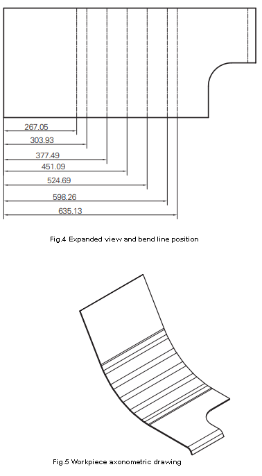
The cross section of the split part is imported directly into Catia, and the software's Generative Sheet Metal Design module is used to generate the part model. Then the bend line and unfolded view are exported, as shown in Figure 4. The axonometric drawing of the part is shown in Figure 5.
Tips on applying collision bending process
Sheet Metal Processing
During production, it was discovered that some parts with a small thickness (about 2 mm) have serious deformations during processing, leading to a significant drop in processing accuracy and failure to meet design requirements. The reason for this is due to insufficient stress release in the sheet.
During laser cutting and blanking, we observed that the part in this batch deformed due to internal stress. This also provides a preliminary method to evaluate whether thin metal sheets with a large radius can be directly bent using the multi-bending process, i.e., observing the deformation of the part during laser cutting.
If the deformation is serious, measures must be taken to release the internal stress, otherwise it will be difficult to obtain a qualified part. If the production cycle allows it, natural aging is an economical and effective method. However, the separate parts undergo aging treatment for a long time, which will inevitably produce floating rust on the surface. Therefore, they must be cleaned or blasted with rust remover, which increases labor and equipment costs.
Therefore, direct use of steel sheets that have undergone sufficient natural aging is the best choice. If the production cycle is not allowed, after the sheet is separated, annealing can also be used to eliminate internal stresses, but the hardness of the material is reduced after annealing. Therefore, it is necessary to comprehensively consider whether annealing is carried out in accordance with the design requirements of the part.
Calculation of c workpiece and expansion d diagram in collision bending
It should be noted that when using the multi-step bending method to process sheet metal with a large radius, the actual conditions of the part must be followed.
That is, the expanded view is calculated using the arc segment after zooming in on the polyline segment. The enlarged view of the part calculated according to the arc cannot be used directly; otherwise, the part will inevitably be out of tolerance after processing.
Part shape detection using multi- step bending process
It is important to note that when using a general comparison matching sheet to detect the arc size of a workpiece processed by bump bending, the matching sheet should be designed as an external gripping type, and the outside of the arc of the workpiece should be used as surface detection.
If the comparison matching sheet is designed with the inner side as the detection surface, and the matching sheet interferes with the polyline segment, it will inevitably cause the matching sheet not to be in place, resulting in detection failure.
Final thoughts
As an ingenious process method, large arc bending has its characteristics of flexibility and efficiency, but it also has its limitations.
Specific problems must be analyzed according to the design and application requirements of the part.
It is necessary to comprehensively consider the production cost and appearance quality of the part to select the processing method.
Step Bending Radi Large