When comparing rounding and chamfering, most people think about the geometric difference between rounding and chamfering, but it is not so easy to define chamfering and rounding.
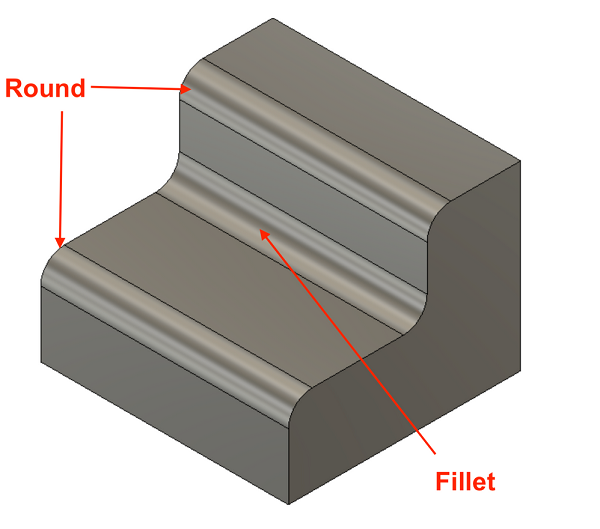
What is the fillet?
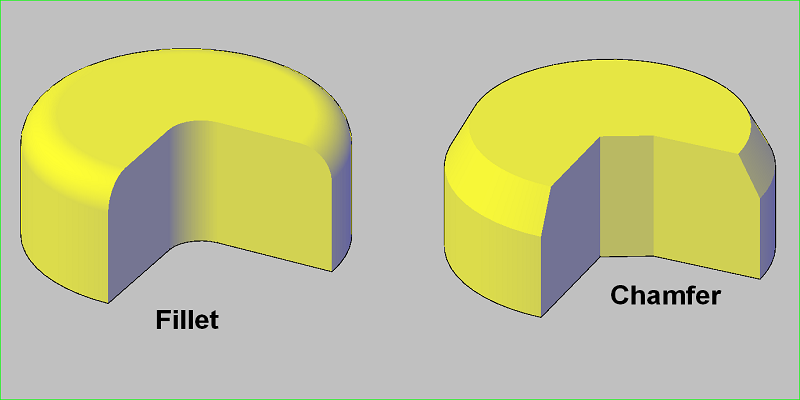
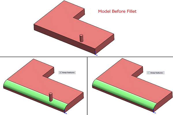
In filleting technology, fillets generally refer to the rounding of the inner or outer corner of a part. It is an edge and a rounded corner of a part and can be on the inside or outside of the part.
When we define a fillet shape, the outer fillet shape is convex and the input fillet shape is concave. The main objective of its use is to reduce the stress concentration factor and uniform stress distribution.
According to the definition of roundness, a roundness generally consists of rounded edges or corners, and the roundness of an inner corner is called a round radius. Rounding radii can be used in casting to improve quality and also to increase load capacity. Therefore, the bend radius is a standard tolerance when designing a casting.
Rounding AutoCAD
The Fillets and Chamfer commands in the Auto CAD definition modify a pair of objects where a chamfer can create a chamfered corner and a fillet can create a curved corner in the middle of two lines.
What is the chamfer?
Chamfer is a beveled or angled corner or edge designed primarily to protect the edge from damage and give the rough edge a more uniform appearance. Let's look at what a beveled edge looks like and why chamfers are used in rounding technology for edges with high stress concentration.
Beveled edges are sharp and straight, not smooth, and are used where stress concentrations are low because they can deform the material. Therefore, they are not recommended for edges with high stress concentrations. For each project, you need to know the difference between chamfers and chamfers, as well as how chamfers work in AutoCAD to compare and make an informed decision. A chamfer is an edge that is sloped at the top and a chamfered edge has a beveled edge at the bottom that can be connected to two surfaces.
What are beveled edges?
A chamfer is an angled or slanted edge or bevel. In mechanical engineering, we can divide chamfers into two subgroups:
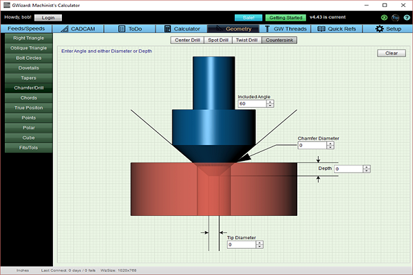
1. Chamfer with 45 degree insert to remove burrs during drilling. Chamfers allow a screw to sit below the level surface of the spruce instead of protruding.
2. A 60 degree chamfer has sharp corners and is not very effective in reducing stress concentrations. Serves as an introduction to screws and nuts. Chamfering is essential after the finishing process of parts to create a groove, groove or chamfer.
When do you need curves and chamfers?
Choosing between fillet mechanics and chamfer forming can increase part efficiency and be cost-effective. It is better to choose according to your design and manufacturability; otherwise, a wrong decision could cost more and shorten the life of the part.
You should know when to use fillets in Solidworks and when it is better to use chamfers in Solidworks. So let's look at the whole discussion if you need fillets and chamfers.
1: You can use a chamfer for a hole where you need to drive screws or bolts. The sharp beveled edge can be helpful for smooth pin movement and fastener insertion. Therefore, using a chamfer in a hole or around the edge of the hole is a good decision. Rounding may prevent the bolt and screw from moving more smoothly.
2: When using the rounding technique, it is difficult to decide on a chamfer or rounding. Sharp edges are not safe for use and may injure the user. Therefore, it is important to remove all sharp edges.
3: Fillets and chamfers can be used for outer edges. This depends on the project requirements and needs. Simple chamfering can be used to break up sharp corners, but it must be safe for your project. Breaking sharp edges can reduce the risk of injury.
4: The fillet tool is best used on the edges of a part. It is suitable for designing external parts that aim to achieve an aesthetically pleasing effect. Consider how much better the design will be if you use a larger radius. A larger radius fillet surface can be effective in relieving stress.
5: When producing CNC milled parts, it is difficult to produce sharp inner corners because the material is cut by a rotating tool. This tool leaves a radius at the corners when rotating. Therefore, you can use rounding on vertical edges. For machining processes, it is advisable to choose the radius of the internal edges greater than that of the cutting tool.
6: What are beveled edges and beveled corners? Chamfered edges, chamfered holes and chamfered surfaces can be used according to project requirements. Simple chamfering can break up sharp corners, but make sure the outside isn't critical in your design. By definition, chamfering is a general machining practice.
7: For inclined and angled surfaces, it is necessary to pay attention to the machining process on 3-axis machines. Angular surfaces are recommended for 3D editing. To make your product more aesthetically pleasing, you need curves on all edges.
How do you decide the rounding radius? This is a very important design decision. According to the definition of radius of curvature, a large radius may cause minor complications. Therefore, when choosing a rounded curve, it is necessary to take into account the size of the radius.
Differences between fillets and chamfers
Some important differences between a rounding and a chamfer are as follows:
● A certain tool size is required to produce different rounding radii. Chamfers, on the other hand, do not require a specific tool size. To produce different chamfer sizes, one tool size is sufficient for the process.
● If we consider the production cost of the machining process, chamfering is cheaper compared to rounding. Therefore, it proves to be more expensive for the production of parts.
● The fillets are safe to use as they have no sharp edges. Champers have sharp edges and should be used with care on all jobs.
● Curves have better stress flow, can distribute stress over a large radius, and protect against deformation. Therefore, curves are a good choice for outdoor pieces. Chamfers have less stress concentration and can cause material deformation.
● Rounding technique requires more processing time compared to chamfering technique. Rounding edges and corners is not easy to produce and requires more time and effort.
● Curves have curved edges, which take more time and are difficult to produce. Casting and forging are simple curve production processes. Chamfering is a quick method and does not require much time to process.
How to choose between rounding and chamfering
Choosing a curve or a bevel is not like choosing a car or a book. You need to pay attention to some important points and your concept of rounding and chamfering should be clear. Or not?
AutoCAD's Chamfer and Fillet commands are primarily used to modify tracks. This command is known for its quick and optimal result. Let's look at how to choose between chamfering and rounding. Both perform the same function, but your selection depends on how you make the components.
Some key points are as follows:
- Creating different chamfers requires a single tool, but creating different radii requires different tool radii for the process.
- A chamfer is a good option for machining parts from a bar or block.
- When machined manually, a chamfer may require less machining time than a round, which requires more machining time.
- Due to their visually appealing properties, fillets are preferred in industrial design.
- For CNC machining Both rounding and chamfering require the same machining time and you only need to change the tool for CNC machining.
- The hole feature in the part design can be useful when choosing between curves and chamfers. If the hole is for inserting a pin, screwing in a part or tightening a screw, you must choose a chamfer.
- Chamfers are considered a good choice for fine machining because they are cheaper compared to roundings.
- With a curve, the coating and color are evenly distributed. Engineers therefore choose curves for protective coatings. Chamfers have sharp corners and reduce layer thickness. Therefore, chamfers are not recommended for protective coatings and paints.
- Compared to chamfers, curves provide lower stress concentration and less resistance.
- A big disadvantage of chamfers is their uneven distribution, which leads to accelerated rust formation.
- Rounding is useful for resolving stress concentrations – a major problem in load-bearing mechanical parts. We can reduce them by adding fillets to lines and points of high voltage areas. Rounds can effectively distribute stress and help create more durable parts. They also increase the part's ability to support a greater load.
Concluding
Round ones have lower stress concentration factors and can protect against warping, while chamfers are more flexible when chamfering mating parts. Therefore, it is very important to understand the difference between the technical definition of chamfers and the definition of curves so that you can choose the correct design and machining method for your project. Comparing chamfer, round, and chamfer can result in a higher quality, more efficient design at a lower cost.