1. Experimental Materials
1.1 Material Performance Parameters
The experiment studied the high-strength steel DP590, whose chemical composition is presented in Table 1, and the performance parameters are presented in Table 2.
Table 1 Chemical Composition of the Material (mass fraction)
| Material Grade | W | Yes | Mn | P | s | Al | You |
| DP590 | 0.078 | 0.03 | 1.76 | 0.01 | 0.004 | ≥ 0.020 | – |
Table 2 Material Performance Parameters
| Parameter | Value |
| Work hardening exponent n | 0.13 |
| Poisson's ratio μ | 0.33 |
| Modulus of elasticity E/MPa | 199,000 |
| Hardening exponent K | 1,003 |
| Yield strength/MPa | 318 |
| Tensile strength/MPa | 626 |
| Yield/traction/% ratio | 50 |
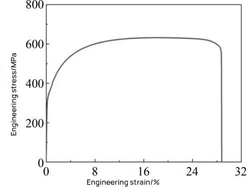
1.2 Stress-Strain Curve
The tensile test was carried out in accordance with the GB/T 228.1-2010 test standard, and the true stress-strain curve obtained from the test data is shown in Figure 1.

two . Finite element model establishment
2.1 Model Establishment
Based on the NUMISHEET2011 international standard case and the size of beam parts commonly used in actual production, the size of the plate used for the U-shaped part is determined as 100mm × 360mm × 1.2mm.
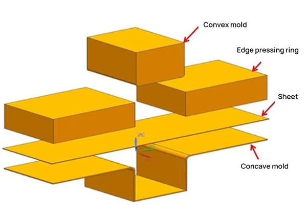
The assembled two-dimensional structure is shown in Figure 2, and the geometric dimensions of the mold parts are shown in Table 3. The model was created in the UG NX software according to the drawing, and the explosive structure was assembled as shown in Figure 3.
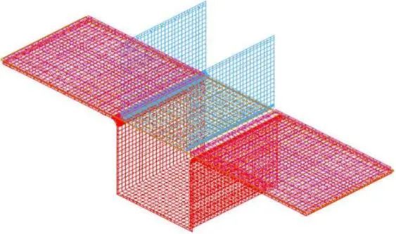
It was then imported into Dynaform for mesh generation and basic process parameter configuration, as shown in Figure 4.
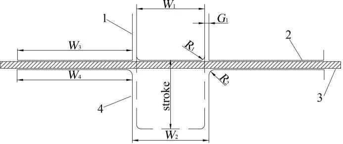
- 1. Punch
- 2. Flanged Ring
- 3. Sheet metal
- 4. Die
Table 3 Geometric Dimensions of Mold Parts
| Parameter | Dimensions/mm |
| W1 | 80 |
| W2 | 84 |
| W3 | 135 |
| W4 | 135.5 |
| R1 | 5.0 |
| R2 | 7.0 |
| G1 | 1.2 |
| stroke | 70 |
2.2 Reasons for Springback and Assessment Standards
During the stamping process, the sheet metal will undergo large elastic deformations.
In the final stage of stamping, unloading the load will cause the previously generated elastic energy to be released, causing the internal stresses to recombine, thus changing the shape of the part. This results in the springback defect of the sheet metal.
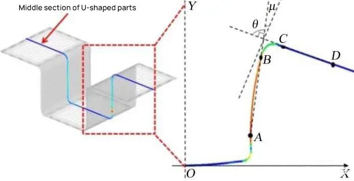
Now, the middle section of the U-shaped part is selected to measure the springback situation, as shown in Figure 5.
The size of the springback is characterized by the complementary angle μ of the angle θ between the surfaces AB and CD. The greater the angle μ, the greater the elastic return amplitude.
3. Investigation of factors affecting the springback angle
The factors that affect the springback of stamped parts are mainly the mold structure, sheet metal shape and mechanical properties, in addition to the parameters of the stamping process.
In view of the structural and stamping process characteristics of the U-shaped part, four main factors, including flanging force, friction coefficient, sheet metal thickness and punch corner radius, were selected to explore the influence of different factors in the variation of the springback angle. .
3.1 Influence of Flanging Force
Under the conditions of using high-strength steel DP590 with a thickness of 1.2 mm and a coefficient of friction of 0.125, and a gap (G1) of 1.2 mm between the punch and the die, the influence of the flanging force on the springback was studied by performing forming and springback simulations with flange forces ranging from 10 kN to 120 kN.
The influence of the flanging force on the springback angle obtained through the simulation is shown in Table 4 and Figure 6.
Table 4 Relationship between Flanging Force and Springback.
| Flanging force/kN | Springback angle(°) |
| 10 | 8,126 |
| 20 | 8,902 |
| 40 | 7,734 |
| 60 | 6,660 |
| 80 | 5,572 |
| 100 | 4,226 |
| 120 | 3,686 |
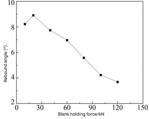
As shown in Figure 6, the springback angle of the part initially increases and then decreases. From Table 4, it can be seen that when the flange force varies from 10 kN to 120 kN, the maximum change in springback angle is 5.216°, indicating that controlling the flange force has a more obvious effect on the angle elastic return.
The reason for the above phenomenon is: when the flanging force is small, the part is mainly formed by bending. The sheet metal produces bending stress under the action of the punch, and the bending stress is released after the punch is discharged, which leads to an increase in springback.
When the flange force increases to a certain extent, the plastic deformation of the material increases, causing the amount of elastic deformation released by the sheet metal to decrease, and therefore the springback also decreases.
3.2 Influence of the Friction Coefficient
Under the conditions of using a flange force of 40 kN and a gap of 1.2 mm between the punch and the die, the influence of the friction coefficient on springback was studied by carrying out forming and springback simulations with coefficients of friction ranging from 0.025 to 0.275.
The influence of the friction coefficient on the springback angle obtained through the simulation is shown in Table 5 and Figure 7.
Table 5 Relationship between Friction Coefficient and Springback.
| Coefficient of friction | Springback angle(°) |
| 0.025 | 8,126 |
| 0.075 | 8,902 |
| 0.125 | 7,734 |
| 0.175 | 6,660 |
| 0.225 | 5,572 |
| 0.275 | 4,226 |
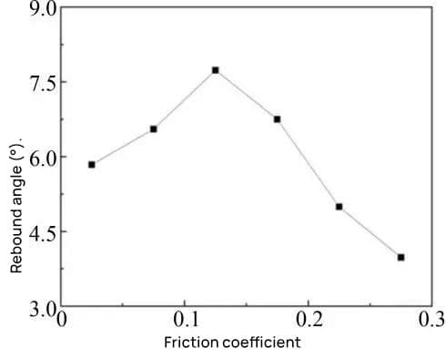
Table 5 shows that when the friction coefficient varies from 0.025 to 0.275, the maximum change in springback angle is 4.676°, indicating that controlling the friction coefficient has a more obvious effect on springback angle.
As shown in Figure 7, the springback angle of the metal sheet increases first and then decreases with the increase of the friction coefficient.
The reason for the above phenomenon is: initially, because the friction coefficient is small, the frictional resistance of the material is small, and the sheet metal forming process is mainly bending, resulting in a large amount of springback.
As the coefficient of friction gradually increases, the frictional resistance of the material also increases. When the friction resistance is large enough, the edge of the sheet metal is difficult to move, and the part forming process is mainly plastic deformation.
After the punch is unloaded, the sheet metal will release less elastic potential energy, and therefore the springback of the sheet metal will decrease.
3.3 Influence of sheet metal thickness
Under conditions of using a flange force of 40 kN, a gap of 1.2 mm between the punch and the die, a coefficient of friction of 0.125 and a punch radius of R5 mm, the influence of the sheet metal thickness on the springback was studied by performing formation and springback simulations with sheet metal thicknesses ranging from 1.0 mm to 1.8 mm.
The influence of sheet thickness on the springback angle obtained through the simulation is shown in Table 6 and Figure 8.
Table 6 Relationship between Sheet Metal Thickness and Springback.
| Sheet metal thickness/mm | Springback angle(°) |
| 1 | 10,541 |
| 1.2 | 7,734 |
| 1.4 | 5,448 |
| 1.6 | 3,814 |
| 1.8 | 2030 |
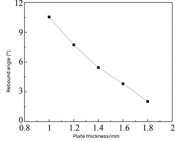
As shown in Table 6, when the sheet thickness varies from 1.0 mm to 1.8 mm, the maximum change in springback angle is up to 8.511°, which is the largest among the four selected factors, indicating that the Controlling sheet thickness has a relatively obvious effect on springback angle.
As shown in Figure 8, the springback angle of sheet metal decreases with increasing sheet metal thickness.
This is mainly because, under the condition of constant punch radius, the greater the thickness of the sheet metal, the smaller the ratio between the radius of curvature and the thickness of the sheet, resulting in less bending deformation of the sheet metal and a lower proportion of elastic deformation in total deformation.
Therefore, when the punch is unloaded, the springback of the sheet decreases.
3.4 Influence of punch corner radius
Under conditions of use of a flange force of 40 kN and a coefficient of friction of 0.125, the influence of the punch corner radius on springback was studied by performing forming and springback simulations with punch corner radii varying from R3 mm to R7mm.
The influence of the punch corner radius on the springback angle obtained through the simulation is shown in Table 7 and Figure 9.
Table 7 Relationship between Punch Corner Radius and Springback.
| Punch fillet radius/mm | Springback angle(°) |
| 3 | 6,388 |
| 4 | 6,982 |
| 5 | 7,734 |
| 6 | 8,153 |
| 7 | 8,553 |

According to the observations made in Table 7 and Figure 9, increasing the punch fillet radius from 3 mm to 7 mm results in an increase in the springback angle from 6.388° to 8.553°.
This behavior is attributed to the increase in the contact area between the punch fillet and the metal sheet, which subsequently increases the bending deformation, leading to a greater springback effect.
However, from Table 7, it is notable that the change in the maximum springback value from 3 mm to 7 mm in the punch fillet radius is only 2.165°, which is the smallest effect among the four selected factors.
This implies a minimal influence of the punch fillet radius on the springback angle.