Guide
Quality control of the cutting process is crucial in the first stage of production for companies. As flame cutting is the main cutting and blanking method, ensuring production quality will have a great impact on the overall cutting and blanking process.
This article focuses on the factors that influence the quality of flame cutting and provides solutions to common cutting problems through process methods.
Despite its importance as the main cutting method for small, medium and large companies, flame cutting has its challenges.
Over the years, flame cutting has evolved and CNC cutting equipment has become advanced and sophisticated. As a result, several methods and process techniques to improve the quality of flame cutting have been developed.
In this article, we use XSuperNEST automatic nesting software to examine the factors that affect the quality of parts cut through flame cutting and ways to improve its yield.
Factors Influencing Cutting Equipment
Currently, the market offers a variety of cutting methods and equipment, such as laser, plasma and water cutting, which offer better cutting quality and production efficiency than flame cutting. Despite this, flame cutting remains popular due to its lower cost and is still widely used as a primary cutting method.
CNC flame cutting machines are being increasingly used in the cutting production process. These machines offer the advantage of hands-off programming, but this feature also makes it impossible for workers to compensate for thermal deformation during the cutting process, leading to deviations in dimensional accuracy.
Furthermore, some factors related to the CNC cutting machine itself can also impact the quality of the cut.
Factors affecting cut quality
(1) Cutting gas selection
The choice of cutting gas has a significant impact on the quality of cuts from flame cutting machines. Currently, the available gases are acetylene, propylene, propane and MPS. Each gas has unique combustion characteristics, leading to different cutting scenarios, and choosing the appropriate gas can maximize the benefits of gas cutting, leading to efficient and economical cutting.
Acetylene flame is characterized by its concentrated heat, high temperature, short preheating time, low oxygen consumption, high cutting efficiency and minimal deformation of components. This makes it suitable for cutting thin sheets and short pieces.
On the other hand, the propane flame has dispersed heat, low temperature and longer preheating time compared to acetylene. It also results in a smooth, flat top edge of the cut and less slag on the bottom edge, which is easier to remove. Furthermore, its relatively low cost makes it an economical option for cutting large pieces of thick sheet metal.
The propylene flame has a higher temperature and shorter preheating time compared to propane, slightly higher than that of acetylene. Its high heat content in the external flame makes it suitable for cutting large pieces of thick sheet metal.
(2) Oxygen concentration, speed and cutting nozzle height selection
In addition to proper gas selection, cutting oxygen pressure, speed and nozzle height adjustment are also crucial factors that affect the quality of flame cutting.
It was observed that increasing oxygen concentration decreases cutting time and reduces oxygen demand, with the same oxygen pressure.
The choice of cutting speed is especially important. If the speed is too high, it may cause quality defects such as flameout, rough cutting and reduced cutting efficiency. On the other hand, if the speed is too slow, it may result in the adhesion of oxidation slag and uneven cutting surface.
Based on practical experience, the best cutting speed should be in the upper-middle to upper-middle range of the cutting nozzle's rated speed. For example, when using a No. 5 nozzle to cut a 40mm steel plate, the rated speed range is 250 ~ 380mm/min, with an average speed of 315mm/min. When dividing the range into 10 levels, the best speed is between 336.6 ~ 358 mm/min, with 340 mm/min being the ideal choice.
The choice of cutting nozzle height also affects the quality of the cut. If the center of the flame is too low, it may come into contact with the surface of the part, causing the cut to collapse, slag splashes to block the nozzle, or even tempering. On the other hand, if the height is too high, the flame cannot fully heat the cut, reducing the cutting capacity and making slag removal difficult. It is generally recommended to maintain a distance of 3 to 5 mm between the center of the flame and the work surface for best results.
(3) Lead cutting and application order
A reasonable cutting order promotes uniform heating of the steel plate and compensates for internal stresses, reducing the thermal deformation of the parts.
When cutting the contour of parts, it is recommended to follow the principle of first in and then out, first small and then large, first round and then square, cross heel, first complicated and then simple, to avoid displacement, deformation and size deviation of the parts.
An appropriate feed position and shape can maintain the notch integrity of the workpiece and improve cutting stability, ensuring contour quality.
In practical production, the input position of the outer contour is usually located on the right side of the bottom of the contour, and the shape of the inner contour is best represented by a circular arc.
Optimized process
Even after perfect configuration and debugging of the parameters of the flame cutting equipment, there is no guarantee that the parts will be cut without defects. The shape of the part, the thickness of the plate, the position of the nesting material and the cutting method can affect the quality of the cut.
For example, flame cut plates can be divided into thin plates (thickness <20 mm), medium thickness plates and thick plates.
Thin boards are easy to pierce during the cutting process, but they are prone to thermal deformation. To reduce thermal deformation and bowing of parts, it is recommended to cut from inside the steel sheet instead of at the edge position. This helps maintain the integrity of the external structure of the steel plate.
Using the “continuous cutting” process can reduce the number of perforations, while the “permanent cutting” process can effectively reduce thermal deformation.
For thick and medium plates, thermal deformation is minimal during the cutting process, but punctures can cause slag and damage to the cutting nozzle. To reduce perforations, it is recommended to preheat the edges before starting to cut. Figure 1 shows the conventional cutting method with edge preheating.
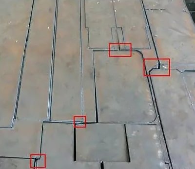
Figure 1 Conventional lead cutting method with edge preheating
(1) Reduced preheat drilling using the “I drilling” process
The conventional edge preheating lead cutting method can effectively solve the perforation problem of thick and medium plate cutting, but it requires a lot of human adjustment in unloading and requires high-quality laying personnel and cutting machine precision.
To solve this problem, XSuperNEST software offers a new “I-drilling process” to optimize the cutting and drilling path.
The punch edge preheat lead cutting method I automatically finds a suitable place to cut a lower circular hole based on the outer contour of the cut part, and uses the circular hole to introduce the next part for preheating, reducing the perforations.
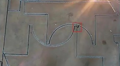
Figure 2 I Perforated Edge Preheat Lead Cutting Method
(2) Using “continuous cutting” process to improve cutting efficiency
To improve material utilization, small parts are often nested within the inner contour of larger parts, and the cutting path usually involves cutting the inner contour part first, then jumping to cutting the next inner contour part, and finally cut the two inner contours separately. This results in low cutting efficiency as the cutting machine has to lift the gun several times and drill the hole several times.
To solve this problem, the cutting path can be optimized using the “continuous cutting” process to reduce the drilling and hollowing process. Figure 3 shows the optimized cutting sequence after using the “continuous cutting” process.
In Figure 3, each part within the inner contour is cut in one row, followed by cutting the inner contour in one row. This allows you to cut parts within the inner contour and inner contour with just one hole, significantly improving cutting efficiency.
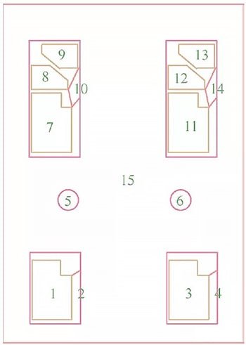
Figure 3 Cutting sequence after optimization of the “continuous cutting” process
(3) Using the “stay cut” process to reduce the thermal deformation of parts
In the process of cutting the inner contour of a part, there may be a mismatch between the actual size and the theoretical size between the inner and outer contours.
For example, as shown in Figure 4, the theoretical dimensions marked for a part with a thickness of 50 mm are 610 mm, but the actual dimensions after cutting are 3 to 5 mm smaller.
This is due to heat build-up when cutting the inner contour, which increases further when cutting the outer contour. Since there is no support on the inner contour when cutting the outer contour, the outer contour is extruded inward by the heat, causing deformation of the part.
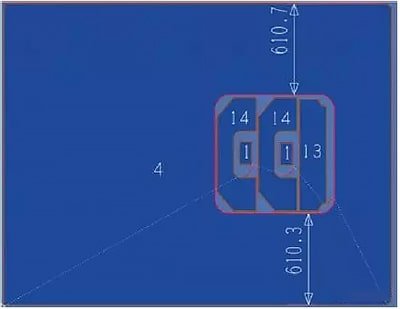
Figure 4 Part grouping diagram
In this situation, adding a “stay cut” process may be a solution.
As shown in Figure 5, the “fixed cut” is added around the inner contour to maintain the contour of the inner contour frame and provide support for the part.
This method effectively reduces cutting errors and improves cutting accuracy, but the disadvantage is that the inner contour requires polishing.
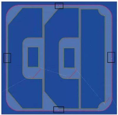
Figure 5 Cutting path after optimization of the “stay cut” process
(4) The use of arc introduction to reduce excessive burning of the inner round hole
The traditional lead-in method involves cutting the outline of the part using a straight line along the straight edge of the outline and then along the straight edge of the lead-in. This does not affect the quality of the cut as long as the beginning of the insertion of the part is straight.
However, when cutting the inner circular hole, the traditional insertion method leads to a lack of smooth transition when cutting directly into the contour, resulting in excessive burning of the contour and affecting the cutting quality, as shown in Figure 6.
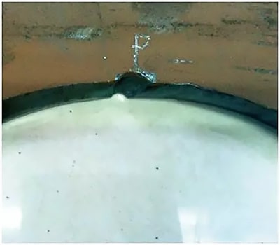
Figure 6 Excessive burning of the inner round hole
During the research process, XSuperNEST introduced the arc introduction method to prevent excessive arc burning and improve the cutting quality of the inner circular hole of the workpiece.
The arc insertion cutting method, shown in Figure 7, uses an arc tangent to the inner circular hole to create a smooth transition, leaving a gap with the initial insertion point and smoothly connecting with a circular arc.
This method has been verified and confirmed to be effective through actual production, as shown in Figure 8.

Figure 7 Circular arc leading to the cut
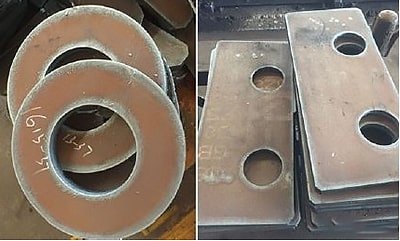
Figure 8 Using circular arcs to guide cut pieces
Conclusion
Molding, as the initial stage of production, is critical to the success of a company. Flame cutting, being the main cutting method, has a direct impact on the quality and productivity of production.
Therefore, it is imperative to effectively control the quality of flame cutting.
There are several factors that affect the quality of the cut, including the equipment itself, gas choice, cutting speed, nozzle height, cutting sequence, and more.
By using appropriate parameters based on actual production conditions, cutting quality can be improved and the rate of qualified parts can be increased.
Furthermore, by optimizing the cutting path through using the appropriate cutting process based on the thickness, contour shape and other characteristics of the parts, the production error of parts can be reduced, the efficiency and cutting quality of parts can be reduced. can be improved, and ultimately the company's production efficiency can be increased.