Function of Sheet Metal Fabrication Hole
The sheet metal fabrication hole is designed to prevent stretching during sheet metal bending.
When the bend line intersects at a single point or is close to the edge of the plate and is less than twice the thickness of the plate, it is necessary to increase the size of the manufacturing hole to prevent bending and stretching.
Fabrication holes are typically used in sheet metal parts that require bending and edge bending. In cases where edge rolling and bending are not required, the need for a manufacturing starter hole can be eliminated.
Disadvantages of not having manufacturing holes:
Without manufacturing holes, the edges and corners of the material will be reduced in thickness and will require filler for welding. This can also result in deformation of the weldment.
Advantages of having manufacturing holes:
In cases of edge wrapping, manufacturing holes can ensure a smooth fold on the rolled edge without bending or stretching.
Hole Drilling Skills in Sheet Metal Bending Process
Determining Fabrication Hole Size:
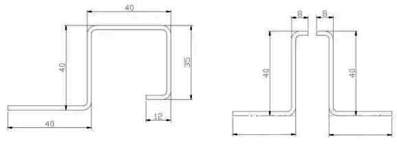
The size of the sheet metal fabrication hole is determined based on its position. If the hole is located at the intersection of two lines, it must be twice the thickness of the plate. The minimum thickness must not be less than 1.5 times the thickness of the metal sheet. When bending thick sheets, the manufacturing hole must be enlarged appropriately to take into account the bend fillet.
Disadvantages of this manufacturing hole:
After bending, especially for thick sheets, there is significant loss of material at the bending angle, making it ugly and difficult to weld. In this situation, it is necessary to improve the hole manufacturing method.
Manufacturing Hole Optimization Method
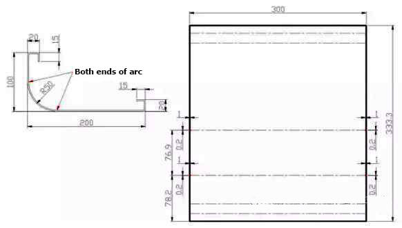
The hole size in sheet metal manufacturing can be determined based on the bending edge and taking into account the plate thickness and bending fillet to avoid possible problems.
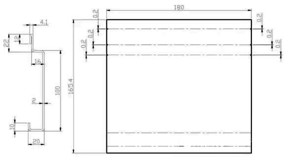
For a visual representation, see the figure below.
The figure above illustrates a square sheet metal box with a thickness of 3 mm and a bending height of 15 mm on all four sides.
Manufacturing Hole Improvement Scheme
Improvement in the Blanking Method:
There are two sheet metal cutting methods, namely punch cutting and laser cutting. Punching results primarily in round holes, with limited ability to produce square or long holes due to mold constraints. In the case of the 3 mm sheet shown in the figure above, laser cutting is used for stamping.
Manufacturing hole shape improvement:
To avoid aesthetic problems after bending, a long strip shape can be used for the fabrication holes.
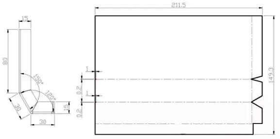
Determining Long Strip Manufacturing Hole Size:
Typically a width of 1 mm is used as it does not negatively affect the appearance or release of sheet metal bending deformations.
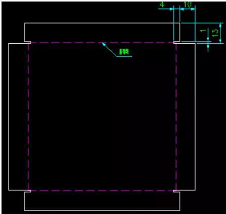
Method to calculate depth dimension:
The depth dimension is calculated as follows: 10 mm equals the bend height minus 3 mm plus a factor of 5 and 4 mm equals the thickness of the sheet metal material plus 1 mm.
Manufacturing hole improvement effect
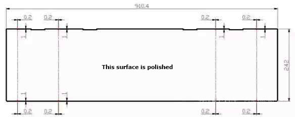
When using this method, the sheet metal part after bending will have a narrow gap of only 1mm. See the three-dimensional rendering for a visual representation.
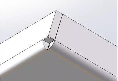
After bending the manufacturing hole made through this method, the bending angle is well controlled and as a result, welding can be carried out without the need for additional filler material.
Why should bending and stretching be avoided?
Bending and Pulling Impact:
(1) Fold size is affected:
During the drawing process, a significant amount of force is required to separate the thickness of the sheet metal. This can cause the part to move and result in dimensional displacement due to the unpredictable direction of the applied force.
(2) The doubled die is vulnerable to damage:
As previously stated, high levels of force are present at sharp edges, which can exceed the support capacity of the matrix, causing it to collapse and damage.
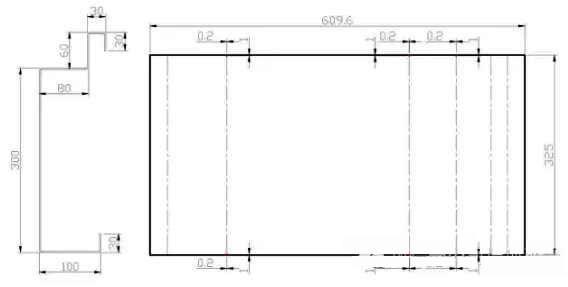
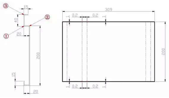
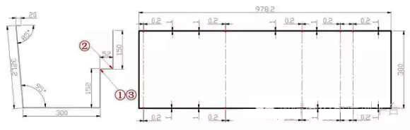
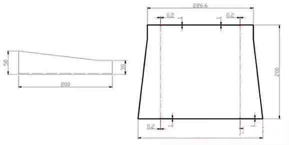
Bending Positioning Manufacturing Hole Application Pattern
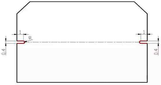
Manufacturing hole size and shape:
- The opening size for the manufacturing hole is 1 mm x 0.2 mm with a root radius of 0.1 mm. This design is suitable for sheet thicknesses less than or equal to 3 mm.
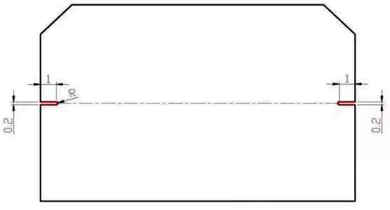
- The opening size for the manufacturing hole is 1 mm x 0.4 mm with a root radius of 0.2 mm. This design is suitable for sheet thicknesses ranging from 3mm to 6mm.
Scope of use:
- Angle Type:
The bend angle is not a perfect 90 degrees and positioning holes are drilled at all bend positions, including overlapping bend points.
- Fitting type:
For appearance parts or butt joint parts with strict accuracy requirements, positioning holes must be drilled in the bending position.
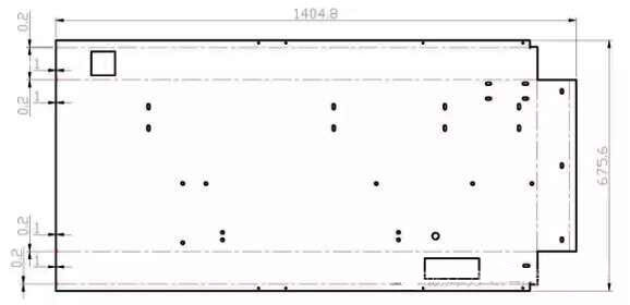
- Large Size Type:
When the bend size exceeds 200mm, all positioning holes must be drilled at the bend position.
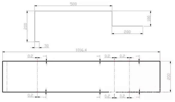
- Continuous folding of various complex types:
For continuous bending of complex parts, positioning holes must be added starting from the third bending edge.
- Bending order type:
For parts that cannot be processed following the standard bending sequence, positioning holes must be drilled in the bending position.
- Repeat fold type:
Due to limitations of bending equipment, positioning holes must be drilled at all bend positions for parts that require repeated bending.
- Do not rely on the stop ruler:
Positioning holes must be drilled in all fold positions for parts that cannot be placed against the stop rule type.
- Guide rail type:
Positioning holes must be drilled in the bending position for guide rail type parts.
- Circular positioning hole:
Positioning holes are drilled at the starting points of the arcs at both ends of the curve.
- Traction plate type:
Positioning holes must be drilled at the bend location of the drive plate components.
- Overlay Type:
The positioning holes must be drilled at the overlapping location of the overlapping components. The positioning hole must be drilled to the specified dimension for continuous bending, based on the overlapping edge.