General formula of threading die structure
For small size threads, a punch is generally used in threading dies, while for larger threads (M5 and above), a punch with pre-made hole is commonly employed, allowing punching and threading to be completed in one go .
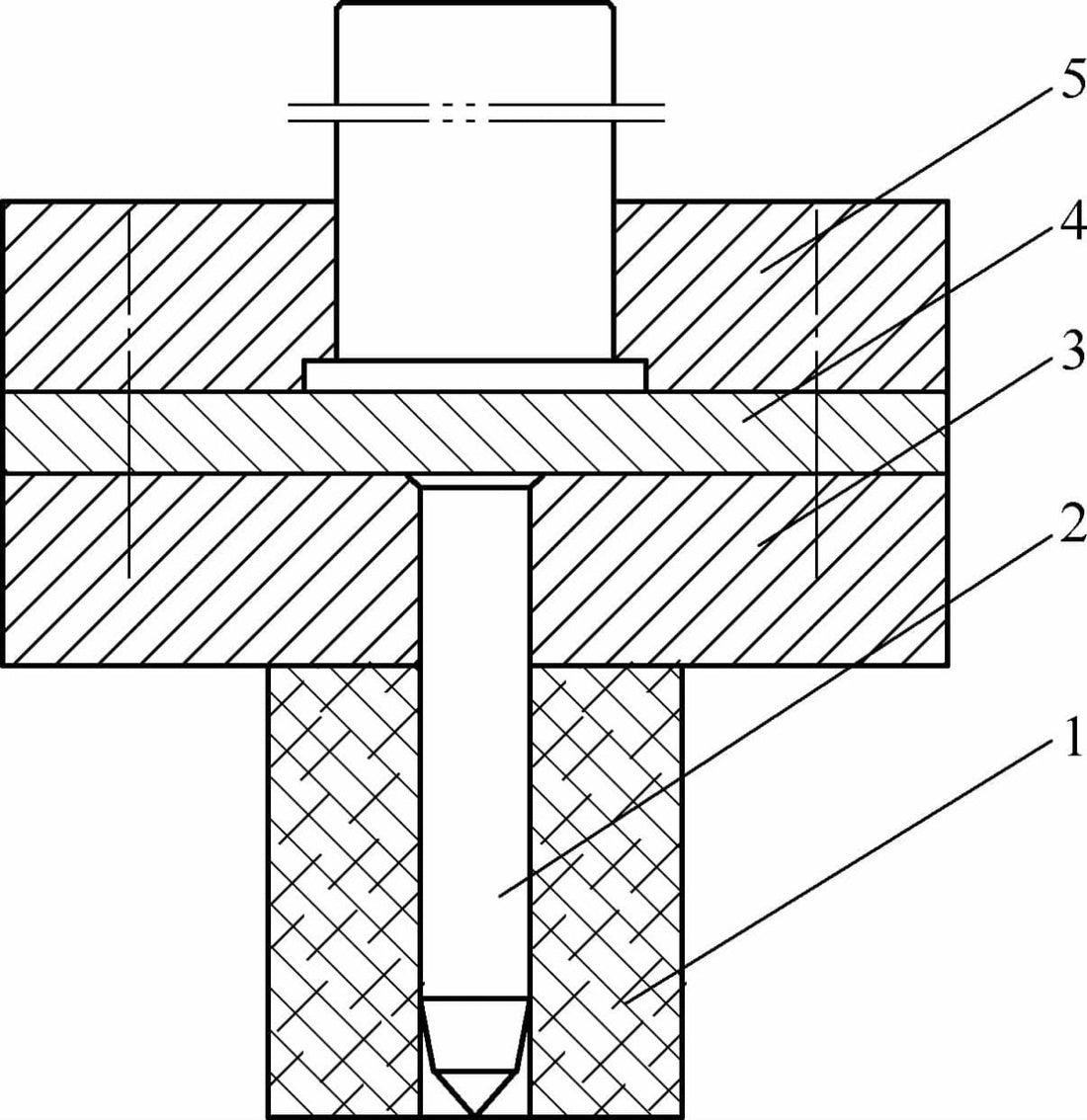
When the punch descends to a set height, the material is torn under the action of the flat cutting edge. In most cases, residual material from the punching process remains attached after tapping, but will loosen on its own after tapping, as shown in Figure 5-20.

1—Rubber elastomer 2—Punch 3—Punch retaining plate 4—Backing plate 5—Top die support
When flanging multiple holes simultaneously in the secondary die, guide posts and bushings must be installed, as illustrated in Figure 5-21.
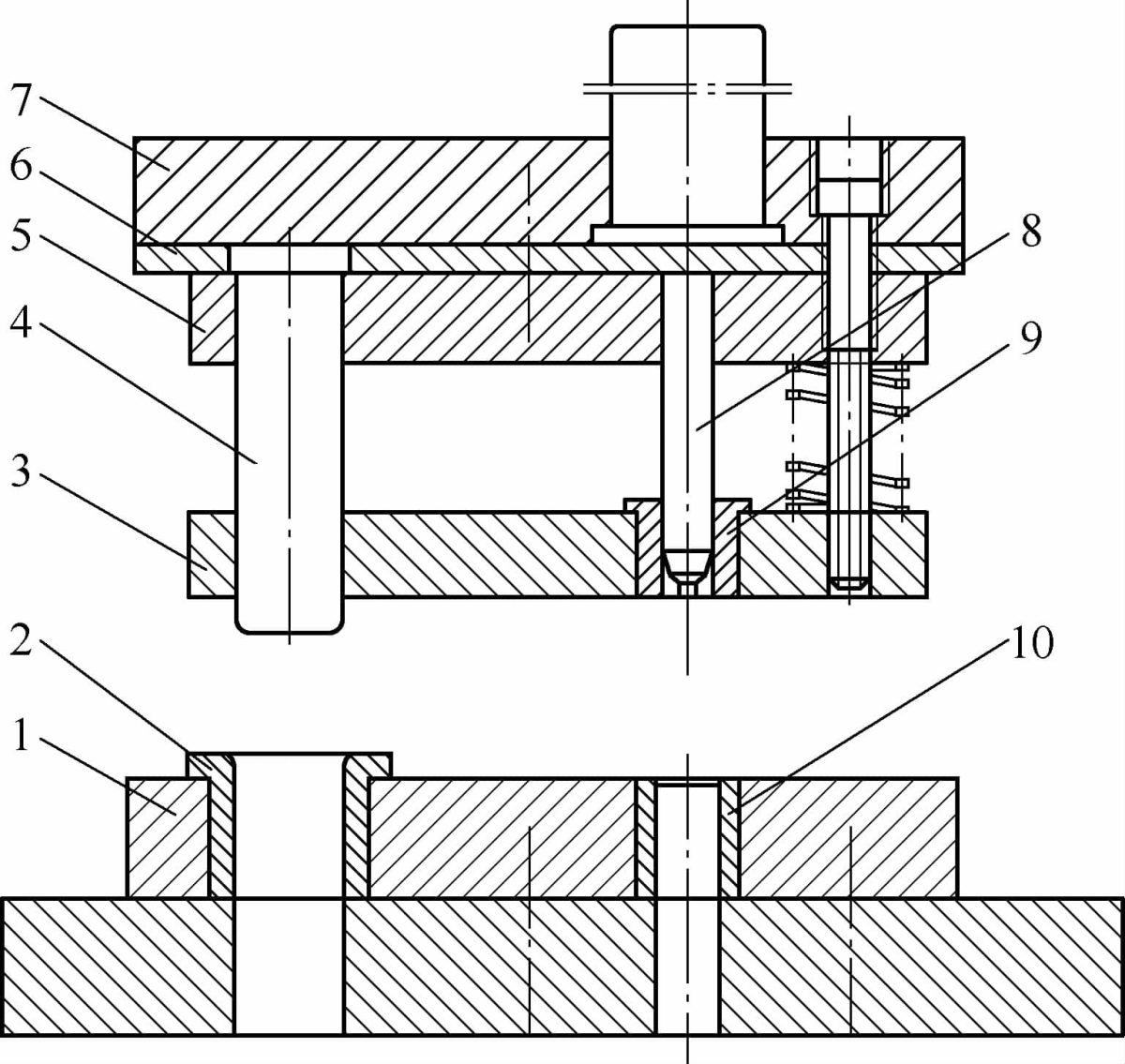
1—Die 2—Guide bushing 3—Removal plate 4—Guide post 5—Punch retainer plate 6—Spacer plate 7—Top die shoe 8—Punch 9—Guide sleeve 10—Hard bonded die insert
For large diameter single hole flange dies with pre-made holes, guide posts and bushings are not required. Centering is achieved by aligning the punch guide section with the prefabricated hole, followed by positioning according to the external shape of the part, as illustrated in Figure 5-22.
1—Die insert 2—Workpiece 3—Die insert liner 4—Ejector ring 5—Upper die shoe 6—Punch 7—Lower die shoe
Flanging and threading dies must generally be equipped with an ejector mechanism to disengage the part from the punch. The workpiece can be easily removed from the die under the action of rebound force, so there is generally no need to consider using a remover.
However, when performing grinding taps with extensive deformation or when the material thickness is ≥4mm, the use of a stripper should be considered, as shown in Figure 5-23.
1—Punch 2—Edge pressing ring 3—Die 4—Lifter.
Asymmetric force flanging die (chrysanthemum vase flat handle)
In theory, asymmetrically loaded flanged parts and asymmetrically bent parts can be processed into symmetrical parts to prevent the part from moving by completing both parts at the same time and then cutting the part in half after flanging.
However, since small parts such as pot handles are often cut from excess material at the edges, which does not satisfy the above conditions, this description mainly focuses on individual flange dies.
During the single bending process, the material is pulled by the one-sided flanging force, resulting in slippage. The key to designing such dies lies in preventing material slippage and ensuring the flange line is positioned correctly.
Before the punch contacts the workpiece, use a movable pressure plate to firmly clamp the workpiece. The clamping force must exceed the flanging force.
Incorporating various compensation factors, the formula for estimating the flanging strength of stainless steel materials is as follows:
In the formula:
- F – flanging force (N);
- L – flange line length (mm);
- t – material thickness (mm);
- Rel. – yield limit, which is set at 280 (MPa).
Currently, most of these types of molds predominantly use rubber elastomers as an elastic element to apply pressure. Rubber elastomers offer significant benefits such as high elasticity, excellent recovery performance and tear resistance.
The thickness of the rubber elastomer is not necessarily better when increased; an ideal thickness is generally three to four times the sum of the flange height plus a certain tolerance.
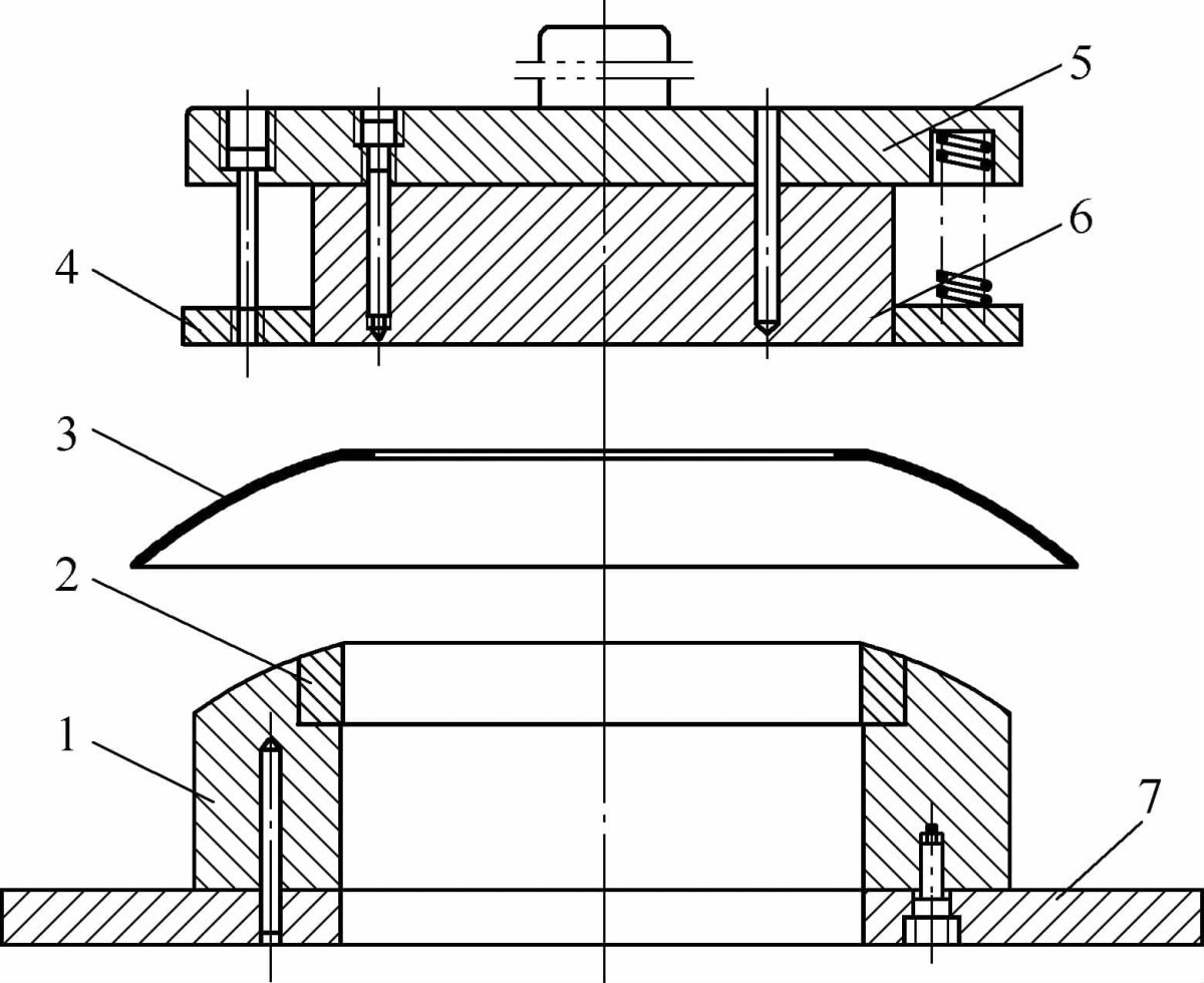
If the pressure within the calculated height is insufficient, thinner rubber sheets can be layered, with thin steel shims interspersed. Increasing the surface area of the rubber can increase the pressure applied. For parts drilled with holes, it is best to use hole placement as shown in Figure 5-24.
1) Rubber elastomer, 2) Force transmission pin, 3) Locating plate, 4) Punch, 5) Blind plate, 6) Die and 7) Lower die support.
Persimmon-shaped pot spout features rolled edge
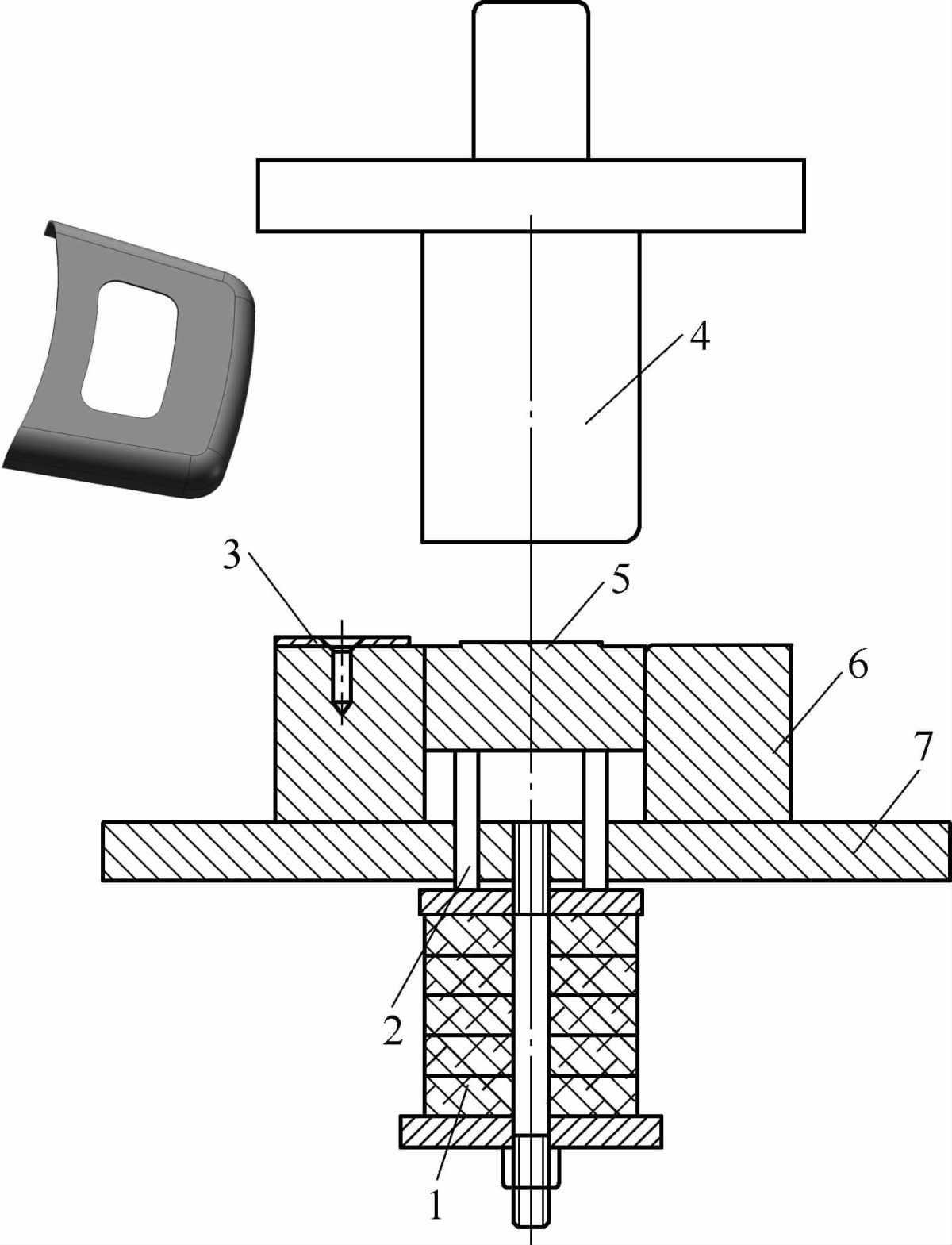
During the brazing process between the nozzle and the body of a persimmon-shaped pan, in order to conserve the expensive silver brazing material, it is necessary to form a vertical flange along the contour line of the larger end of the pan body. The spout flanging operation is carried out in a bench-top cantilever press, with the die placed in an inverted position, as shown in Figure 5-25.
1. Kettle body, 2. Punch retaining plate, 3. Plate holder, 4. Die, 5. Punch, 6. Elastic element, 7. Cantilever workbench.
During operation, place the pre-drilled kettle body 1 into the punch die 5 with positioning features. As the die 4 descends, it overcomes the resistance of the spring element 6 to flange the workpiece. When the upper die rises, the lifting plate 3 is lifted by spring force, releasing the part from the flanging position.
At the design stage, it is essential to ensure that the vertical distance between the kettle spout and the cantilever bench exceeds the travel of the flange to avoid damage to the spout.
Flanging instead of curling (flanged spout of a kettle)
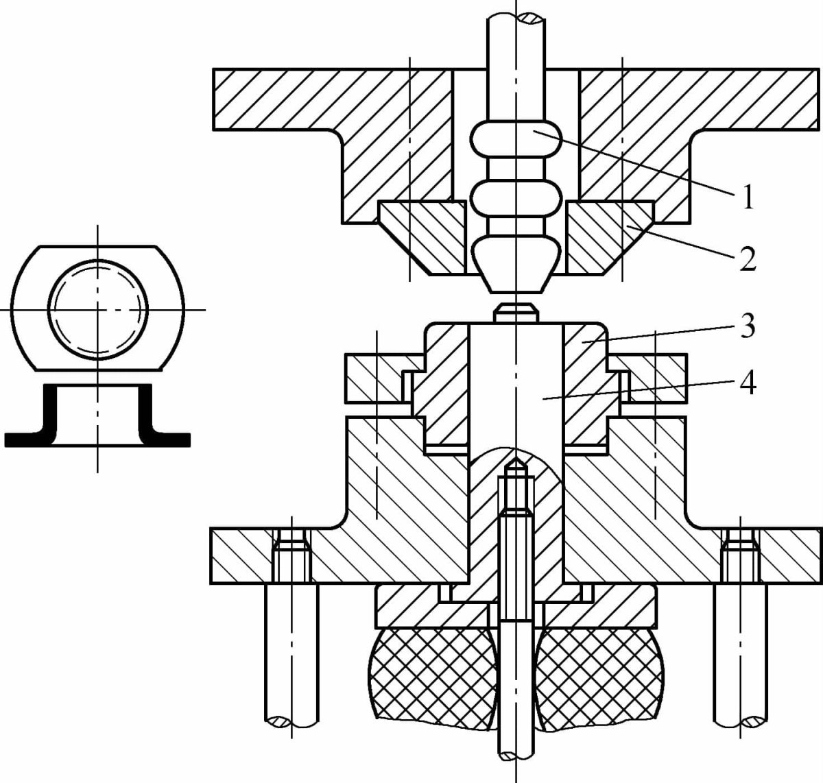
In the production of stainless steel kettles, the spout is commonly processed using a double flange technique, as shown in Figure 5-26. During design, the height of the first flange should be moderate, ranging from 4 to 6 times the material thickness. The height of the second flange must not be too small and must vary from 8 to 12 times the thickness of the material.
At this stage, the clearance on both sides of the punch and die should be increased to 1.5 to 2 times the material thickness. During the second flanging process, the edge formed by the first flange will automatically be pressed tightly against the second flange, creating an effect similar to a wavy edge.
1. The effect after piercing the kettle body. 2. The first flanging. 3. The second flanging.
Hard Die Edge Flanging
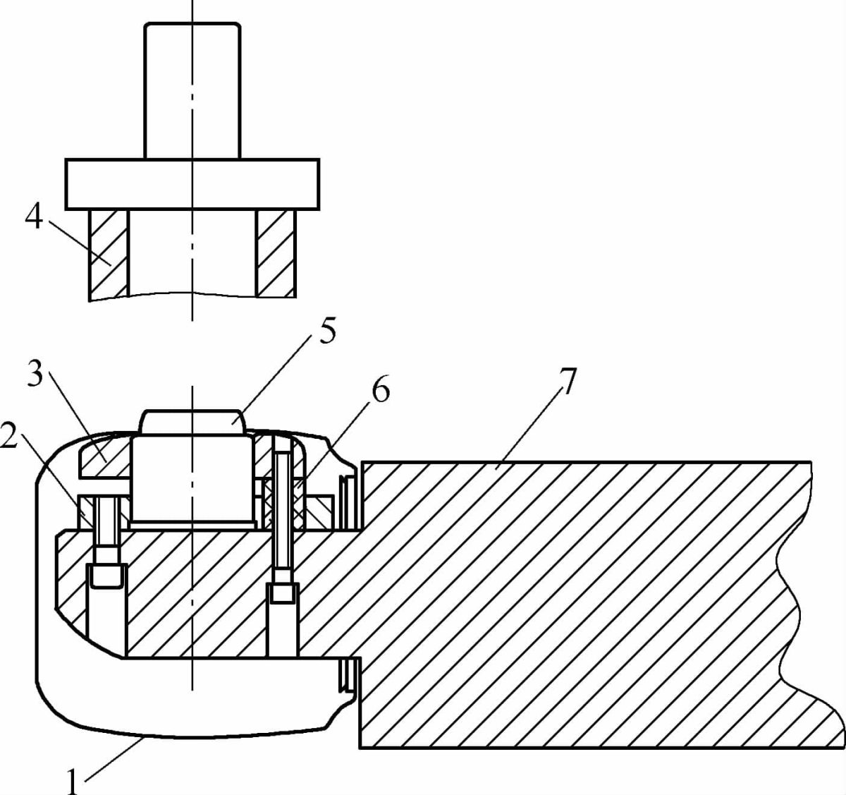
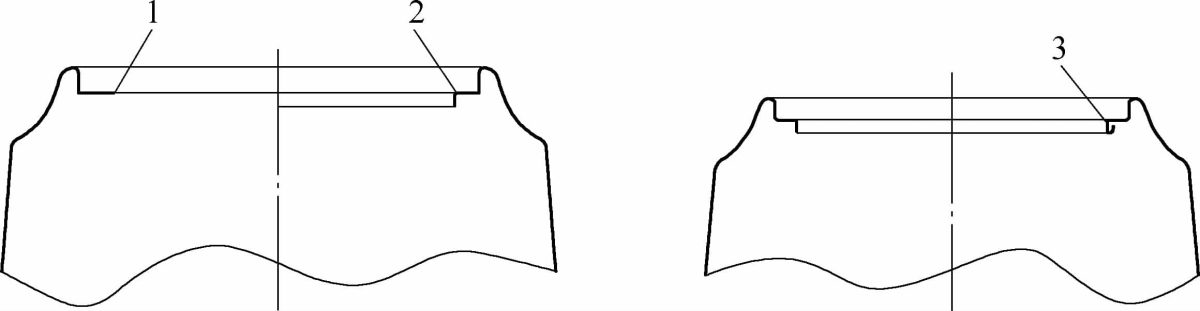
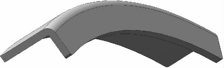
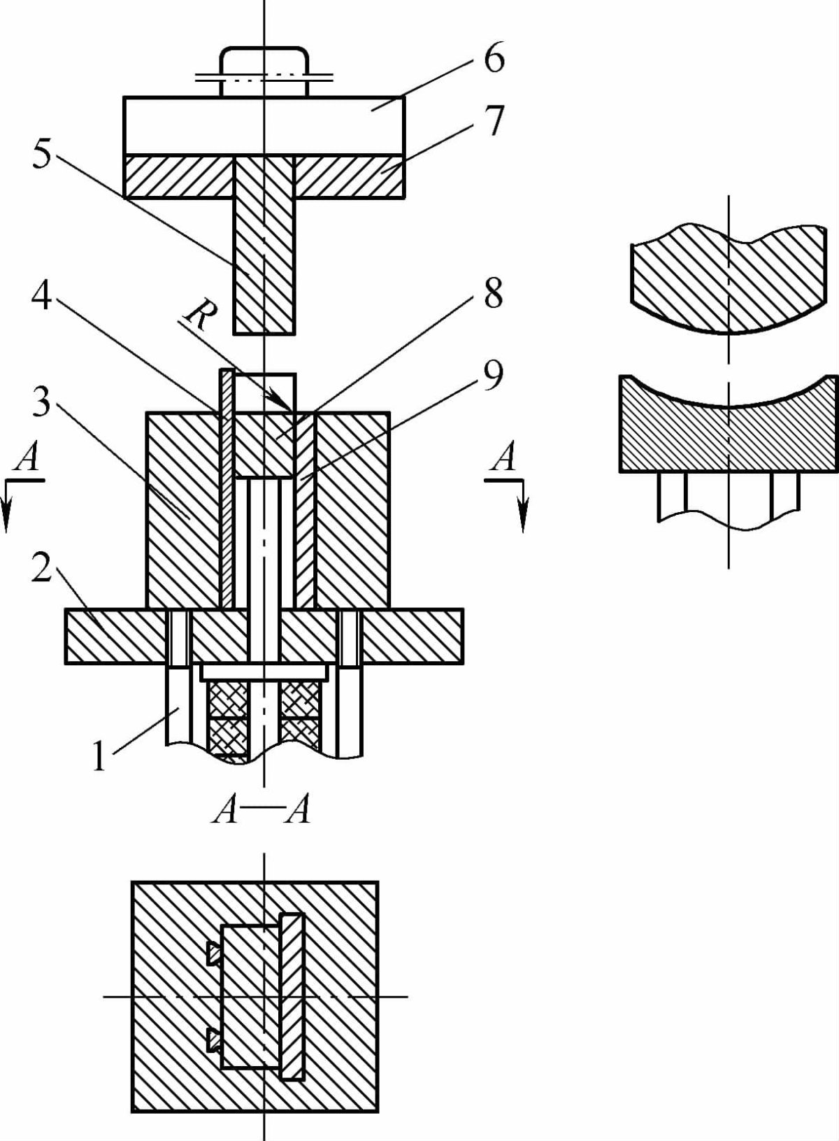
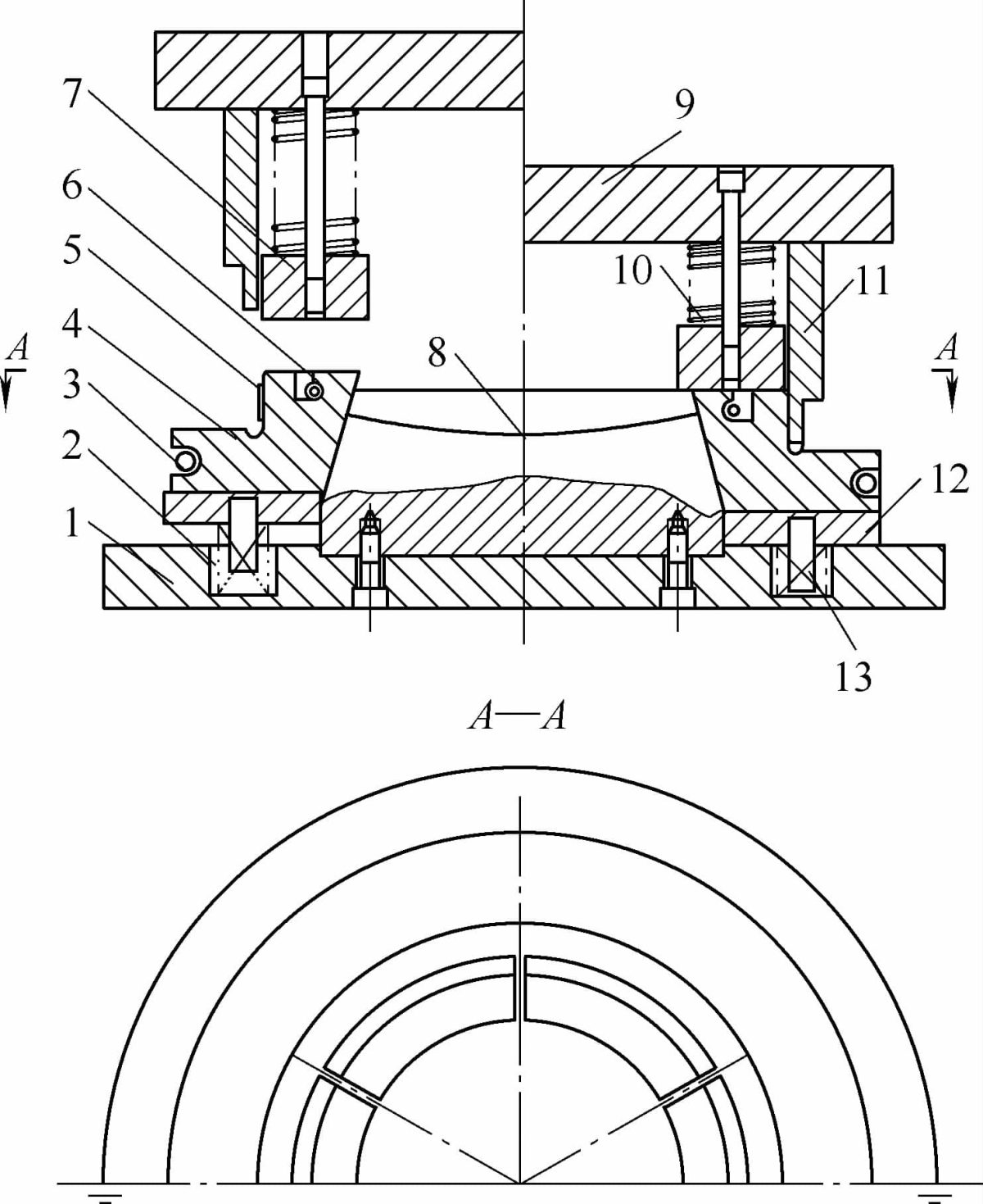
Figure 5-27 illustrates a flanged part with a rounded arc, with a material thickness of 1.0mm and a flange height of 12mm. Based on experience, to avoid wrinkling under compression, the flange height H should not exceed 14 times the thickness (H≤14t). The formation matrix is shown in Figure 5-28.
Typically, to increase operational reliability, the punch arc should be slightly longer than that of the workpiece, with the lower die being 6 to 10 mm wider than the upper die.
The die insert (3) can be made of low carbon steel. The working surface of the wear plate (9) is rounded to mainly serve the function of the die corner radius (R). Processing it as a separate component can reduce the consumption of die steel or high-speed tool steel, decrease manufacturing difficulty, and allow fine-tuning of the clearance between the punch and die.
The perforating and stripping plate corresponds to the product design. The working edge of the wear plate is parallel to the die shoe. The material is gradually formed during the downward stroke and finally ejected from the cavity by the removal plate.
Pipe flaring with punch and cantilever ball method
The tube can be flared outward using a cantilevered punch with a steel ball. The mold structure schematic is shown in Figure 5-29, which is suitable for flanging after a prefabricated hole has been processed into the pipe material.
The mold working process is as follows:
First, place a steel ball of the appropriate diameter inside the pipe at the puncture (drilling) location, then place the pipe horizontally, fit the punch over it and press the steel ball. At this point, turn on the press and as the upper die moves downward, it forces the punch to move downward, pushing the steel ball through the tube.
After the return of the upper die, the punch rises automatically, is removed from the tube and thus the entire flanging process is completed.
The structure of this mold is simple and practically unrestricted in the length direction, but the cantilever strength of the mold is limited by the inner diameter of the steel tube. Flanging can be performed on thicker pipes with an internal diameter of 40 mm or greater.
In this design, a rubber elastomer is added below the top die to reduce noise; and the limit screw can be adjusted to set the punch height.
1. Ejector mechanism 2. Lower die base 3. Die insertion 4. Locator 5. Punch 6. Upper die base 7. Punch retainer plate 8. Removal plate 9. Rigid plate
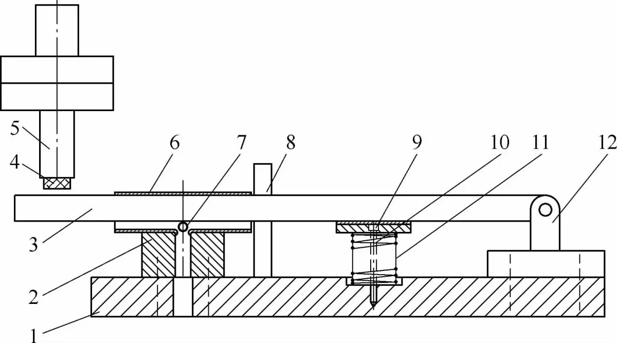
1. Die holder, 2. Concave die, 3. Pressure rod, 4. Rubber elastomer, 5. Upper die, 6. Tube material, 7. Steel ball, 8. Tube material positioning stop, 9. Push rod lift seat, 10 . Limit Screw, 11. Spring, 12. Bracket.
Quick-change chuck for converting inside diameters to outside diameters, featuring a metal mesh liner ring
Figure 5-30 illustrates a skimmer mesh mouth forming die, which can also be used to manufacture wrap rings for metal mesh sheets from other cylindrical components, such as engine air filters.
The main parts of the die consist of an expansion cone (8), expansion blocks (4), return springs (3 and 6) and a lower die base (1).
Expansion blocks are sized according to the internal diameter of the part after forming. They are made from material that has been heat treated and then machined.
These blocks are divided into equal sections and specific gaps are cut to ensure that, once contracted, they maintain a reasonable clearance with the prefabricated ring. The return springs (3 and 6) squeeze the expansion blocks (4) when they are free.
When the prefabricated ring (5) is fitted over the expansion block (4), the die is in the reset position and the external diameter of the expansion block (4) is smaller than the internal diameter of the prefabricated ring ( 5).
As the upper die moves downward, the pressure block (7), driven by the strong spring (10), overcomes the upward force of the spring (2), forcing the expansion block (4) to move downward. and expand outward, increasing your external strength. diameter until it fits snugly against the inner diameter of the workpiece. When the expansion block descends completely, its external diameter stops increasing.
The upper die continues to descend, pushing the prefabricated ring (5) into the R-groove to gradually form it. The compressed material flows upward along the outer diameter of the upper die, forming a new outer diameter and creating a gap designated with the original diameter to accommodate the metal mesh sheet.
As the upper die rises, the part remains in the lower die, and the expansion block, under the combined action of the spring (2) and return springs (3 and 6), contracts in diameter, facilitating removal of the piece.
By adding or removing shims (not shown in diagram) below the support plate (12) or expansion cone (8), the diameter of the expansion blocks can be adjusted.
This die operates reliably and does not require high-quality raw parts; can even be used with welded material rings.
1 base, 2 springs, 3 and 6 return springs, 4 expansion blocks, 5 preformed rings, 7 clamping blocks, 8 expansion mandrels, 9 upper mold bases, 10 heavy duty springs, 11 upper molds, 12 support plates, 13 pin spring centers
Upper and lower flange die
Figure 5-31 illustrates an upper and lower flanging die suitable for flanging thick materials.
Pipe End Flange Forming
Pipe end flange forming is a specialized forming process that has evolved from traditional stamping flanging techniques. It involves applying axial pressure to the tube through a die to induce localized bending deformation at the mouth edge of the tube.
This technique allows the manufacture of parts with the advantages of simplicity, fewer processing steps, lower cost and high quality, and can even produce parts that are difficult to obtain with other stamping methods. This process has been widely adopted in industrial sectors such as automotive and aerospace.
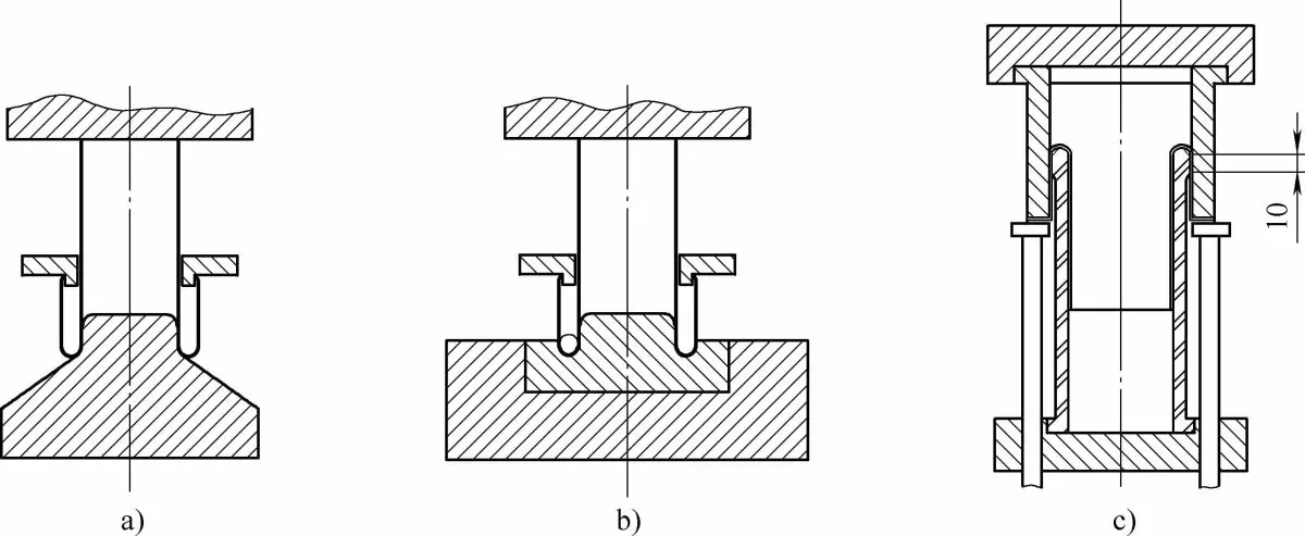
There are two basic methods of forming pipe end flanges: external flanging and internal flanging, as shown in Figure 5-32.
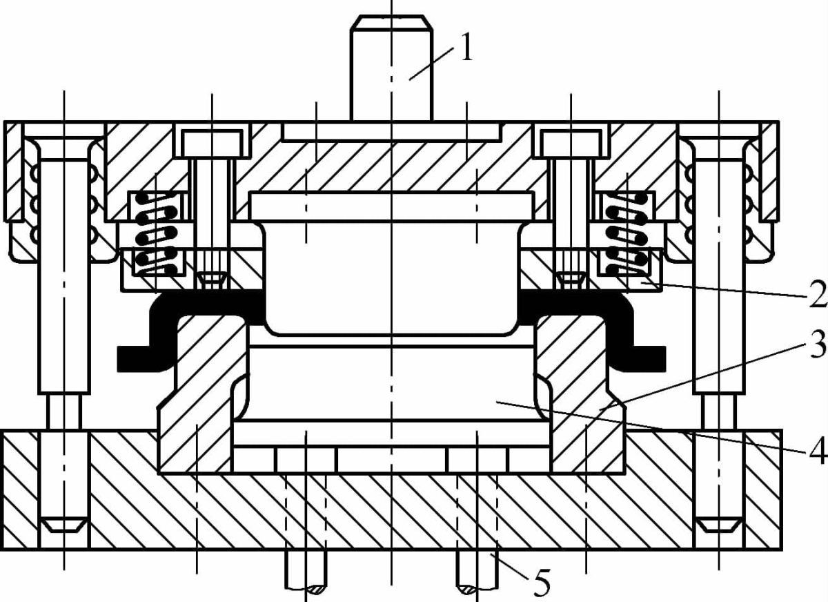
1 – Punch, 2 – Stripping plate, 3 – Die, 4 – Lifter, 5 – Spring ejector.
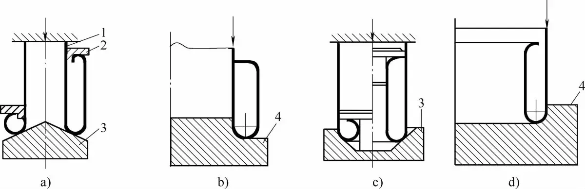
a) and b) External Flange; c) and d) Internal Flange.
1. Tube mold 2. Guide ring 3. Conical die 4. Fillet die.
The tube rolling process not only effectively forms a variety of double-walled cylindrical tubes and multilayer tube components, but also processes convex bottom cups, stepped tubes, special-shaped tubes, as well as double half-wall tubes, annular tubes doubles. wall cylinders, double wall hollow nuts, heat exchangers, automotive mufflers and waveguides used in the electronics industry.
Currently, these components are generally manufactured using multi-step stamping and welding methods, which are difficult, expensive and produce poor surface quality. The lamination process guarantees reliability, lightness and material savings for these parts.
A wide variety of tubular materials are suitable for the rolling process, including aluminum alloys, low carbon steel and austenitic stainless steel. Tubes with sizes ranging from 5mm x 0.5mm to 250mm x 5mm can be successfully rolled into double layer tubes.
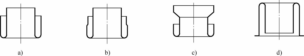
a) Cone-shaped rolling tube, b) Tube rolling + rolling, c) Tube rolling + flaring, d) Stretch rolling tube.
Tube spinning is a complex deformation process that involves the transition from flaring deformation to curl deformation and then to rotational deformation. To ensure a smooth transition between deformation modes, it is essential to satisfy the mechanical, geometric and plasticity conditions during deformation. The main process parameters include rotational force, die semicone angle, relative tube wall thickness, and plasticity conditions of the tube material.
1) External Turn
Under axial pressure, the tube blank rotates from the inside to the outside, transforming the inner wall of the tube into the outer wall. This process increases the diameter of the tube. Although the external pressure load slightly thickens the tube wall, the circumferential tensile stress produced by external rotation is stronger, leading to a thinner tube wall.
The mold types for external tube spinning mainly include conical dies, annular groove dies and stretch spinning dies. When processing double-layer tubes using conical or annular dies, the upper part of the mold not only applies pressure to the tube material, but also needs to be equipped with a guide ring to direct the material that has already been rotated.
a) Conic Matrix.
The conical die is the most representative type of rotating die. When designing a conical die, the main consideration is to determine the angle of the semicone (a) to satisfy the wiring conditions. Based on stress-strain and plasticity calculations and considering the influence of material stretching, the semicone angle (a) must meet the following condition: 22.5° ≤ a ≤ 55°.
Similar to tube flaring, the maximum outer diameter of the spun tube is also limited by the stretching rate of the material. In principle, the size of the spinning diameter can be freely chosen between the material stretching rate and the minimum curl radius.
When a large diameter difference is required before and after spinning, a larger semicone angle should be used. Conversely, a smaller semicone angle should be selected when a smaller diameter difference is required.
Conical dies are versatile, have low friction, simple structures and are easy to manufacture. However, when the tube blank deforms in a conical die, it tends to slide, making accurate centering difficult.
The spinning is in a state of free deformation, determined only by the principle of minimum strength and stress balance, and is significantly affected by the non-uniformity of the material structure, making it difficult to produce high-quality tubular components. To prevent the tube end from slipping in the conical die, a cylindrical guide feature can be added to the cone head, resulting in a noticeable improvement, as shown in Figure 5-34a.
a) Conical locating die b) Slotted radius die c) Extensible flare die
(b) Annular groove radius mold.
Radial corner groove die is a type of tube flaring die derived from tube end flanging (flange) die. In a conical die with a positioning boss, the intersection of the boss and the tapered surface is made at a conical transition to facilitate curling and deformation of the tube blank. This matrix has excellent centering properties.
As the tube material is enlarged, it is constrained by the radius r of the circular groove, resulting in consistently high-quality tube components, as shown in Figure 5-34b.
The design of radius corner groove die mainly involves determining the radius r of the circular groove. The size of r not only determines the restraining effect on the deformation of the tube blank at the radius corner, but also determines the geometric interference between the flare and the undeformed part of the tube blank.
Therefore, it is a critical process parameter that must be greater than or equal to the minimum bending radius of the material and less than or equal to the allowable radius based on the elongation rate of the material.
When designing the corner and groove die with radius, it is not necessary to calculate the radius r. Instead, it can be supplied based on experience and the dimensions indicated on the drawing.
For stainless steel pipes, the minimum bending radius is normally
R=3t
where t is the thickness of the material.
The maximum pipe flare diameter for general piping is
d=D(1+1.4A)
And for welded pipes, the maximum pipe flare diameter is
d=D(1+1.3A)
where:
- d – the tube widening diameter (mm)
- D – the diameter of the tube blank (mm)
- A – material elongation rate (%)
(c) Stretch flanging die.
When performing pipe flanging with the mold types mentioned above, defects such as instability-induced wrinkling or bending of the flanged section may occur. This is because the tube blank is under compressive stress during deformation. In contrast, the stretch flange mold places the deformed section of the pipe blank under tensile stress when subjected to external load, thus completely eliminating the phenomenon of wrinkling during flanging.
Furthermore, the deformation zone is determined by the shape of the mold, allowing the dimensional accuracy of the part to be fully controlled by the mold. Therefore, for tubular components with strict dimensional accuracy requirements, an extensible flange mold must be used.
To reduce frictional resistance in the already flanged section, the useful length of the mold outer diameter should be between 8 and 12 mm, with the remaining sections hollowed out as shown in Figure 5-34c.
Before the stretch flange mold begins operating, the end of the tube is first expanded into one face of the flange to serve as a clamping surface during stretching. Consequently, the outer diameter of the tube formed by the stretch flange mold is always smaller than the maximum outer diameter allowed by the material's elongation rate.
(2) Internal Flange
During internal flanging, the raw tube is rolled from the outside to the inside, resulting in a smaller outer diameter after forming.
1) Rigid die internal flanging.
The rigid die inner flange is rarely used in production practices. This is because internal flanging is much more difficult compared to external flanging. The process of forming internal flanging is one in which the material thickens continuously.
During this thickening process, the crystalline structure of the material must be reorganized. The force required to rearrange the crystal lattice is more than four times greater than the tensile stress required to stretch the material (tensile strength).
As the flow resistance of the material is always lower than the force required to rearrange the network, the pipe material becomes unstable and wrinkles even before entering the flanging process, making it impossible to complete the internal flanging.
In fact, there are many alternative techniques to internal flanging, including using smaller diameter tubes for external flanging, roller hemming, and diameter reduction by cutting followed by internal stretching and flanging (see Figure 7-21).
Among the methods mentioned above, the most commonly used is external flanging of small diameter pipes, which involves using the inner diameter size of the empty pipe as the required inner diameter size of the pipe component, while the size after flanging outside becomes the diameter of the component.
2) Roller inner flange.
When using rollers for internal flanging, there are certain limitations between the thickness and diameter of the material; specifically, a D/t ratio ≥ 200 is required for the process to proceed smoothly. Otherwise, the resistance caused by the aggregation of the material may be excessive, resulting in a polygonal outer diameter of the part.
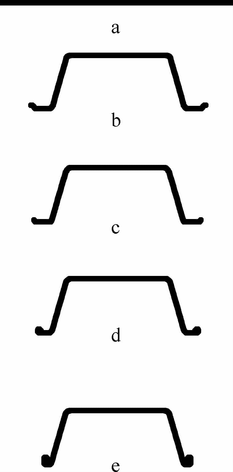
a) Cutting of the circular sheet b) Drawing c) Cutout d) Flange e) Sheath
Bowl Forming Process
A bowl is essentially an enlarged version of a basin designed to increase capacity. To increase its strength, a flange step is added to the rolled edge, as illustrated in Figure 5-35.
The rolling process is strategically placed before flanging to prevent wrinkling of the flange. Although the mechanism of deformation of the rolled section during flanging is not yet fully understood, it has proven to be practically effective.