
In recent years, the use of industrial robots has seen a rapid increase, particularly in the areas of welding, spraying and handling. However, there are relatively few applications of industrial robots in the area of sheet metal bending.
Bending sheet metal is a widely used and dangerous task, making the market outlook for robotic bending machines very positive, with numerous success stories abroad.
Currently, 40-50% of bending machines in European and American sheet metal processing workshops are equipped with robotic automatic bending systems, while in China bending automation is just beginning. Over the next decade, demand for bending robots worldwide will increase linearly.
The numerically controlled flexible sheet metal bending cell, with a robot as the main executing component, is a combination of highly automated equipment that features high efficiency, quality and flexibility.
In this flexible bending cell, choosing the right combination of components can increase bending efficiency and flexibility.
Bending accuracy depends on the accuracy of the bending machine, the positioning accuracy of the robot and the coordinated control between the robot and the bending machine.
The challenge in collaborative control lies in synchronizing the speed between the robot and the press brake and in supporting the robot's movement path of the part.
Poor tracking performance can severely affect the bending angle and flatness of the sheet surface, thus affecting the quality of the final product.
Bending composition of robotic cell press brake
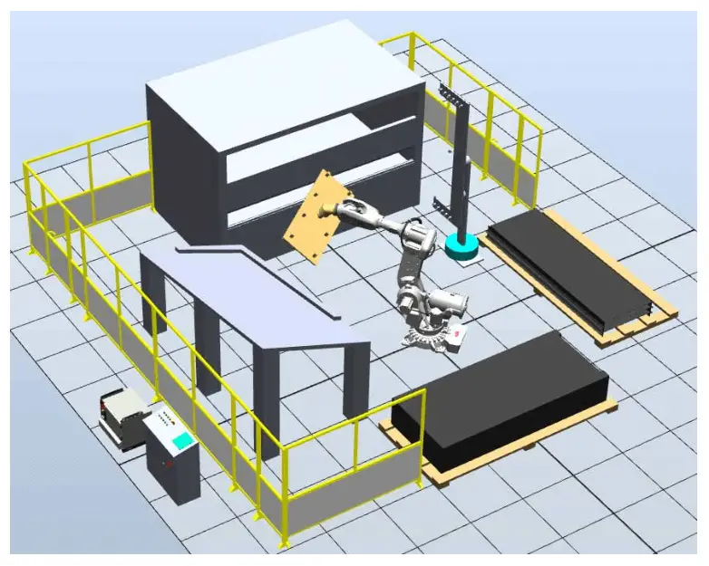
The standard press brake bending cell (Figure 1) is a system that relies on robots and press brake machines as its main components. Other supporting components include a gripper, a loading table, an unloading table, a positioning table, a rotating frame, a manual switching device, and various sensors for detection.
The gripper acts as the robot's “hand” and performs the task of picking up and positioning the part, replacing the role of a human operator.
Fig.1 General layout of the press brake bending cell
The gripper of a bending robot is typically made by attaching several suction cups to a metal frame.
Loading and unloading platforms typically use stacked pallets or conveyor belts or rollers to transport raw materials and transfer finished products.
Oil-coated leaves are prone to sticking, which can result in multiple leaves being picked up at once. To prevent this, a dividing device such as a magnetic divider and detection sensors can be installed near the loading table to ensure that each sheet is grabbed separately.
The positioning table is an inclined platform with flanges and has micro convex spheres. The robot transfers the steel plate to the positioning table and the plate slides down to the holding edge due to gravity.
Because the position of the positioning table and holding edge are fixed, when the robot picks up the sheet again, the position of the plate and gripper is relatively accurate, providing a reference for the next bend.
The swivel frame is a fixed frame for the gripping device. When the robot needs to change its position to pick up the workpiece, it can be placed on the rotating frame for stabilization and the robot can hold it again in the new position.
In some special cases, press brake dies can also be used to clamp the workpiece and change its gripping position.
Robotic bending cell working process
The work of the bending cell is divided into six processes as shown in Fig.2, including:
- Feeding
- Recovering
- Alignment
- Turn
- Doubling
- Palletizing

Fig.2 Bending cell workflow
(1) Food
The complete stack of sheets to be processed is placed manually on the feeding table. A sheet detection switch is installed on the feeding table to prevent the robot from picking up the tray after all sheets have been processed.
(2) Recovery
The robot moves to the location of the loading table and uses an ultrasonic sensor installed in the gripper to detect the height of the plate. Based on the detected data, the robot will automatically adjust its position to pick up the sheet.
After the sheet is grasped, the thickness of the sheet is measured using a thickness measuring device to prevent the robot from picking up multiple sheets at once, which would result in processing failure.
After the thickness measurement is complete, the alignment process can begin.
(3) Alignment
The robot moves to the location of the positioning table and places the sheet on it for precise positioning (Figure 3).
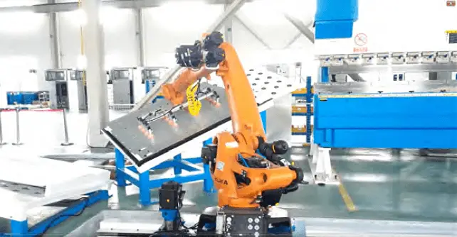
Fig.3 Sheet positioning
After positioning, the robot will pick up the sheet again and prepare it for bending.
(4) Turn
Based on the process requirements, the robot will determine whether a rotating structure is necessary.
If necessary, the robot will go to the location of the rotating structure and place the sheet on it. The robot will then release the sheet and move to the other side of the sheet to pick it up.
(5) Flexion
The robot moves to the location of the press brake machine, places the sheet flat on the lower die, and precisely positions it using the rear finger sensor on the press brake.
Once positioning is completed, the robot sends a bending signal to the press brake and works with it to complete the bending operation.
The robot then evaluates whether another bend is necessary to determine whether consecutive bending should be performed, as shown in Figure 4.
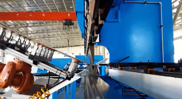
Fig.4 Robotic sheet bending
Bending is the critical process.
The technical challenge of bending lies in the cooperation between the robot and the bending machine, known as following bending.
When the robot grabs or supports the sheet during bending, the sheet becomes deformed. The robot must follow the movement of the leaf and make circular movements according to a specific trajectory algorithm, maintaining a consistent position in relation to the leaf.
(6) Palletizing
The robot moves to the location of the unloading table. Based on the differences in workpiece shape, there are various palletizing methods, including traditional die palletizing, single and double layer cross palletizing, positive and negative buckle palletizing and so on, as shown in Figure 5.

Fig.5 Sheet palletization
Technical key points of bending cell robotic press brake
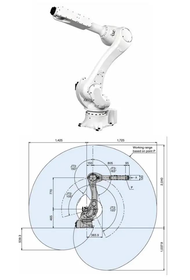
At present, whether it is a general standard six-axis robot or a bending robot optimized for the bending process in terms of arm span or shape, it requires the support of a bend following algorithm, and it is rare to find a robot that does not do it. have a flexural tracking capability.
If the following effect is not good, the clamp or suction cup may deform the workpiece due to the poor following trajectory, causing wrinkles on the sheet and affecting the forming quality.
Developing an accurate model of the robot's bending and tracking motion can help create a strong tracking trajectory algorithm, resulting in excellent tracking performance.
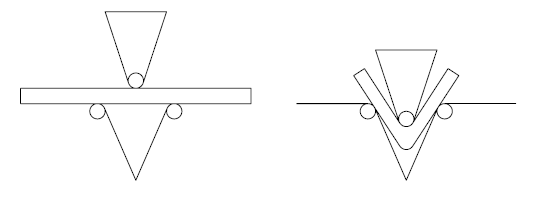
Fig.6 Schematic diagram of the bending process
Figure 6 is a schematic representation of a bending process, and a following mathematical model of bending is derived from it, as shown in Figure 7.
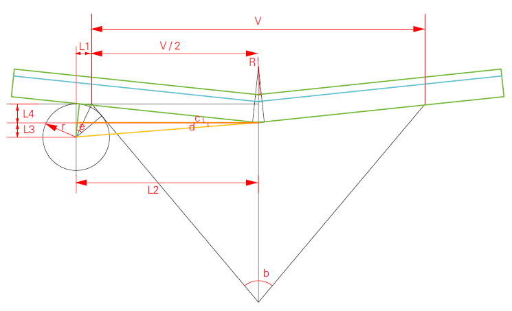
Fig.7 Flexion movement model
Each parameter in Figure 7 is expressed as:
- 1) Upper punch arc radius: R, unit: mm;
- 2) Lower die arc radius: r, unit: mm;
- 3) Die bottom opening: V, unit: mm;
- 4) Mold bottom angle: ∠b, unit: °;
- 5) Part thickness: T, unit: mm;
- 6) Thickness of the neutral layer to the upper surface of the part: λ, unit: mm;
- 7) Part bending angle: ∠a, unit: °;
- 8) The amount of press brake ram that descends from the fixing point: S, unit: mm.
The relationship between the bending angle and the amount of downward bending calculated according to the mathematical model is:
S = (r×TAN(45°-1/4×∠b)+V/2)×SIN(90-1/2×∠a)-(r+R+T))/COS(90-1/ 2×∠a)+(r+R+T)
Based on the mechanical parameters in Table 1, a formula describing the relationship between the bending angle and the amount of descent can be used to calculate the trajectory curve of the bending angle displacement change from 180° to 10° in the and Z Directions, as shown in Figure 8.
Table 1 Bending die information and required workpiece information
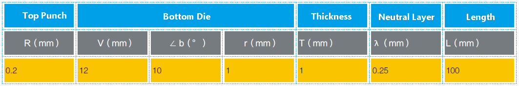
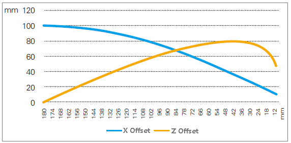
Fig.8 Relationship between bending angle and robot trajectory
Final thoughts
As sheet metal manufacturing continues to advance, the use of robotic bending is becoming increasingly widespread.
Compared with developing specialized bending robots, creating a robot bending tracking model algorithm that is compatible with general six-axis robots and can be applied to a variety of robots will have lower development costs.
By collaborating with top-notch robot brands and other relevant hardware in the industry, the implementation of robotic bending can be rapidly promoted.


