With the rapid development of aviation, aerospace, energy, automobile, household appliances and other industries, the production and use of hydraulic presses has increased significantly in factories.
As society evolves towards humanization, the safety system of hydraulic presses must be safe, stable and reliable while being humane. Safety protection measures used in hydraulic press applications are particularly crucial.
This post aims to briefly discuss various safety protection measures to prevent the sliding block of a hydraulic press from falling.
Sliding hydraulic locking device
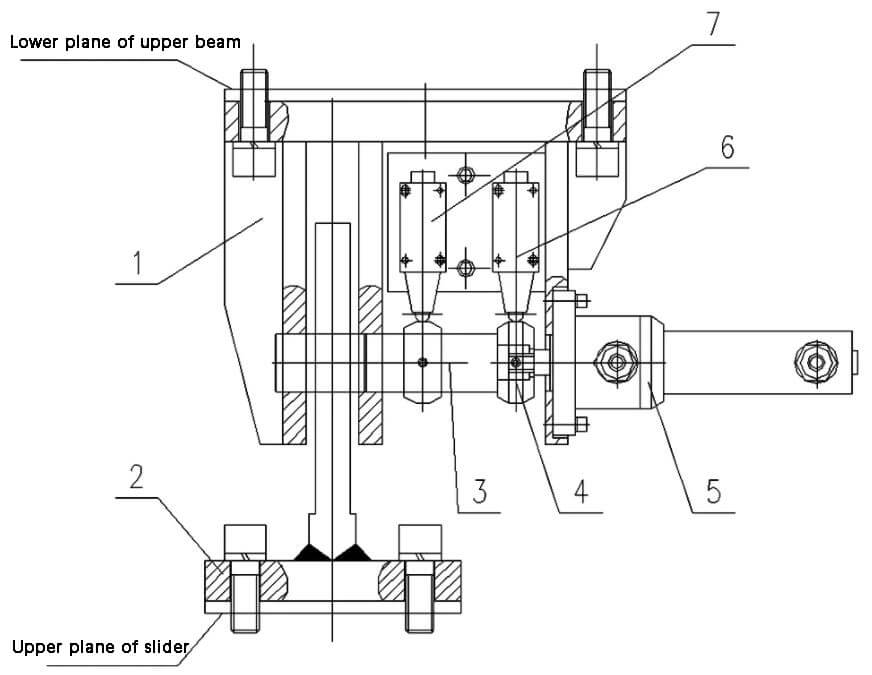
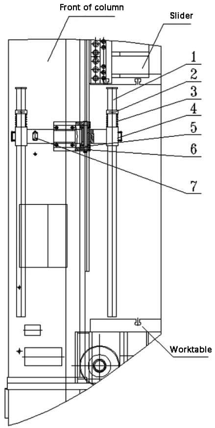
The slider hydraulic locking device is normally installed on the upper surface of the slider and the lower surface of the upper crossbeam, or on the side of the column, as illustrated in Figure 1.

- 1 – upper bracket
- 2 – lower bracket
- 3-lock pin
- Block of 4 impacts
- 5 – hydraulic cylinder
- 6 – loosen the limit in place
- 7 – on-site blocking limit
Fig. 1 Schematic diagram of the slide locking device
The sliding locking device is composed of several components, including upper bracket, bottom bracket, locking screw, impact block, hydraulic oil cylinder, limit switch, screw, washer and others.
For installation, the lower bracket is fixed to the upper plane of the sliding block by means of bolts and washers, while the hydraulic oil cylinder is connected to the upper bracket. The locking screw and firing pin are then attached to the oil cylinder rod, and the upper bracket is fixed to the lower plane of the upper cross beam by means of screws and washers.
When the impact block comes into contact with the limit switch, the switch sends a message indicating whether the device is locked or unlocked in place. For a physical representation of the slide locking device, see Figure 2.
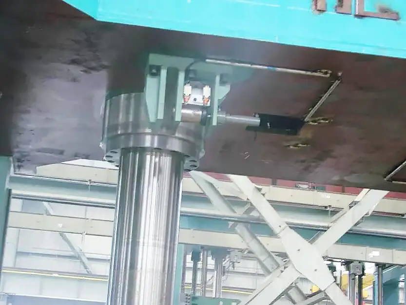
Fig. 2 Physical drawing of the slide locking device
Locking action: When the main slider is in the upper limit position, pressing the lock button will activate the locking device and lock the main slider automatically.
However, if the main slider is not in the upper limit position, pressing the lock button will cause the slider to first rise to the upper limit position and then lock automatically.
Release action: If the slider is in the upper limit position and the locking device is engaged, pressing the release button will immediately unlock and release the slider.
If the locking device is engaged but the slider is not in the upper limit position, pressing the release button will cause the slider to slowly return to the upper limit position before unlocking and releasing.
Hydraulic Support Safety Circuit
To prevent the sliding block from falling out of control, a double support safety circuit is installed in the lower chamber of the main piston oil cylinder to ensure safety.
Figure 3 shows the schematic diagram of the double hydraulic support safety circuit. The circuit comprises the support valve, solenoid ball valve, solenoid valve, overflow valve and piping system.
When the ball solenoid valve (2) and solenoid valve (3) are not energized, the support valve (1) and support valve (4) remain closed, preventing the oil in the lower chamber of the oil cylinder from flowing out of back to the oil tank. This ensures that the sliding block does not move downwards.
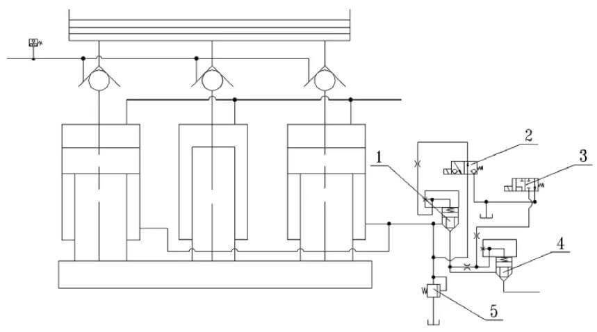
- 1 – support valve
- 2 – electromagnetic ball valve
- 3 – solenoid valve
- 4 – support valve
- 5 – overflow valve
Fig. 3 Schematic diagram of the hydraulic double support safety circuit
Security screw device
Figure 4 shows the structural diagram of the rotating safety screw device.
The fixing ring (2) is fixed to the pillar (1) using a fixing screw and the support (6) is fixed to the front of the pillar using a screw and washer. The swivel arm (4) is fixed to the bracket (6) through the pin shaft (5), and the pillar (1) is inserted into the circular hole at the outer end of the swivel arm (4). Furthermore, the spring (3) supports the weight of the fixing ring (2).
The limit switch (7) is positioned on the front of the column.
The rotating arm (4) can rotate around the axis of the pin (5) as the center. When screwing the column (1) to the work table or outside the column, it sends a signal to the limit switch (7) and interlocks with the host action.
- 1 support
- 2 retaining rings
- 3 springs
- 4 swivel arm
- 5-pin shaft
- 6 brackets
- 7 limit switch
Fig. 4 Structural diagram of the rotating safety screw
To start the operation, rotate the column (1) out of the column using the swivel arm (4) and secure it firmly. Once this is done, the limit switch (7) will send a signal and the press will be able to enter normal working mode.
When repairing the mold or press, screw the bracket (1) into the work table area and press it onto the work table with the weight of the slide and mold. The bracket (1) will support the weight of the slide block, mold, piston rod, plunger rod and other moving parts. If the limit switch (7) does not send a signal, the press will not be able to enter any working mode to guarantee the operator's safety.
The safety screw device is generally located on the front diagonal of the column, which is convenient for rotational operation. It can also be placed on the inner side of the column, and the structural forms are relatively diverse. The specific structural shape of the security bolt can be reasonably selected according to the specific situation.
Safety claw device
Fig. 5 is a schematic diagram of the safety claw device.
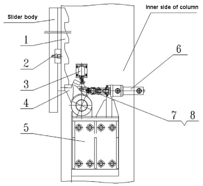
- 1 rack
- Key of 2 flats
- 3 limit switch
- 4 jaws
- 5 brackets
- 6 cylinders
- 7 – connecting rod
- 8 spring
Fig. 5 Schematic diagram of the safety claw device
The rack (1) is positioned with a flat key (2) and fixed to the side of the sliding block with screws and washers.
The claw (4) is mounted on the bracket (5) using a pin shaft, while the oil cylinder (6) is mounted on the same bracket (5) with screws and washers. The claw (4) is connected to the oil cylinder rod (6) through a connecting rod (7), a spring (8), etc.
The bracket (5) is securely fixed to the inside of the column using screws and washers.
The oil cylinder (6) has a rod cavity for oil supply, which drives the claw (4) for release. At the same time, the limit switch (3) sends a signal, allowing the slider to move downwards.
The oil cylinder (6) also has a rod cavity for oil discharge. When the claw (4) is repositioned by the spring (8), it locks into the rack (1) and holds the slider in place.
If the limit switch (3) does not send a signal, the cursor cannot move downwards, thus ensuring operator safety.
Systema Unit
A Systema safety locking device can effectively prevent the sliding block from falling, as shown in Figure 6. The Systema (3) is installed and fixed on the upper plane of the upper beam by means of a connecting plate (4), screws, washers, etc. . The tie rod (1) passes through the System (3) and the upper beam and is connected to the sliding block through nuts (6) and flanges (5). Additionally, a protective cover (2) is installed on the upper surface of the Systema (3).
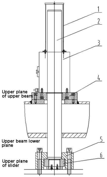
- 1 – protective cover
- 2-tie rod
- 3 setsma
- 4-connection board
- 5 flanges
- 6 nuts
Fig. 6 Systema safety locking device
The Sitema safety clamping device is used to guarantee the protection of personnel and prevent accidents in the event of failure of the supporting machine, by improving the connection between the load and the tool. Provides protection against accidents in the event of a leak or failure of the hydraulic or pneumatic pressure system.
The safety clamping device is designed to hold the slider in any position within the stroke in a mechanically stable and reliable manner.
The self-reinforcing fastening device is based on a design principle that guarantees a high level of safety. As shown in Figure 7, the pull rod (1) is surrounded by a plurality of wedge-shaped clamping jaws (3), and each wedge-shaped clamping jaw is enclosed within a frame (2) mounted with a liner. guide rail (4) and a transmission gasket (5).
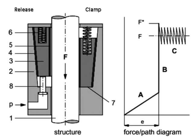
- 1 riser
- 2 racks
- 3-wedge claw
- 4 – guide rail covering
- 5 – transmission lining
- 6-spring
- 7 – maintaining position
- 8 – piston
Fig. 7 Diagram of the structural principle of the Systema
When pressure (P) is applied to piston (8), spring (6) compresses and holds the wedge claw in an elevated position, allowing the pull rod (1) to move freely.
When pressure is released from the piston (8), the safety clamping device comes into action immediately. The spring applies pressure to the wedge clamping claw (3), which then clamps the pull rod (1) to secure the loading device.
However, the clamping force is not generated until the load force moves the pull rod (1).
Due to the self-reinforcing static friction force on the pull rod (1), the wedge-shaped clamping claw (3) moves to the clamping position and stops at position (7) after traveling a distance of “and ” (approximately 5-15mm depending on project diameter).
This movement is referred to as phase A in the force/path.
Conclusion
The above briefly discusses several common safety measures to prevent the slide block of a hydraulic press from falling.
However, there are many other safety protection measures for hydraulic presses, such as installing a safety light curtain at the front and rear of the machine, installing two-hand operation buttons, emergency stop buttons, and machine interlock functions. hydraulic and electrical systems. These measures will not be described in detail here.
At present, the safety protection measures of hydraulic presses are essentially perfect and meet the safety requirements of social and human development of hydraulic presses.