In the production of locomotive parts using sheet metal bending, many parts cannot be produced directly according to design drawings. As a result, it becomes necessary to add turnbuckles, positioning or special bending assemblies during blanking and remove them after bending to achieve the desired result.
This post mainly covers the process-related problems and solutions in bending processing, which is divided into three sections.
The first section provides an overview of bending processing methods, the second section discusses possible process-related problems and their corresponding solutions in bending processing, and the final section summarizes the main points.
Overview of bending processing methods
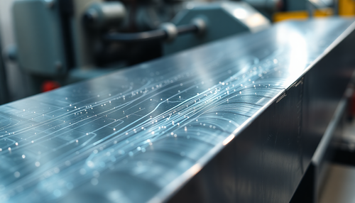
Bending is essentially a cold deformation process used to mold plates into specific shapes. It is a pressure processing method carried out at room temperature. Bending can be used on a variety of materials, including metallic, non-metallic and composite materials.
During this process, the part is processed by a bending die and a hydraulic press brake. The dimensional accuracy of bent parts is guaranteed by upper and lower dies and bending equipment. The process involves applying a bending force to the upper matrix of the sheet metal, generating a reaction force at the support point of the lower matrix and forcing the sheet metal to deform, creating a bending moment.
The final bend angle of the sheet metal is determined by the depth of the upper die into the lower die. Figure 1 illustrates the main working parts of the NC press brake, including the back stop, upper die and lower die.
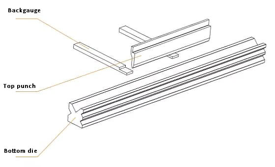
Fig. 1 Main working parts of the press brake
The back gauge is an operating component that regulates the positioning of the bend line.
The upper and lower dies are used to manage the bend angle and inner radius of the workpiece.
Part qualification is mainly determined by these three parts.
Possible process problems in bending and their solutions
In the production of locomotive parts, many bent parts cannot be produced directly according to the design drawings. Therefore, it becomes necessary to add some stretchers, positioning or special molds during blanking, which can be removed after bending to obtain the desired product.
Typical situations requiring process stretchers are summarized below.
Edge collapse generation and prevention
As shown in Figure 2, insufficient material on one side of the part prevents the material from being placed in the lower matrix, resulting in the collapse of some structures during bending. This clearly does not meet the design requirements.
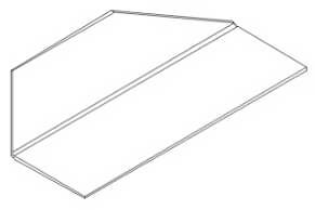
Fig. 2 Folding edge structure
As shown in the structural detail of Fig. 3, generally, when this angle α is less than 50°, there will be a problem that cannot be bent. Process measures must be taken to prevent it and ensure that the workpiece is qualified.
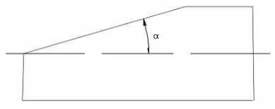
Fig. 3 Workpiece with easy collapsing edge
Process schematic for resolving edge collapse
Figure 4 shows the general process tying scheme, and the double dotted line part is the defined process tying.
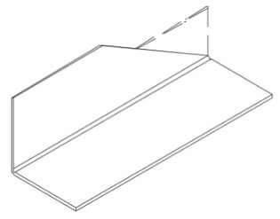
Fig. 4 Process reinforcement scheme
Figure 5 shows the detailed drawing of the tying process.
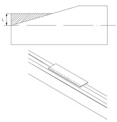
Fig. 5 Detail of the process structure of easy-to-collapse parts
If the length of the part is sufficient for material retention and positioning after the bending process, it is normally defined as L ≥ 0.6 mm (where V is the size of the lower die opening).
It is essential to ensure that the sheet can be placed on the bottom die and extends beyond the edge of the die by at least 3mm.
If the length of the workpiece is insufficient, a link bar is generally added to match the width of the original workpiece structure. This approach not only solves folding problems but also ensures accurate positioning.
Solution to the difficulty in positioning the bend line
As illustrated in Figure 6, some parts designed for positioning have sharp corners or their straight edges, intended for positioning, are too short. This makes it difficult to locate the bend line accurately during the bending process.
To achieve accurate positioning of the bend line, you need to add a process structure.
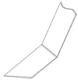
Fig. 6 Positioning of the bending line
Solution: Fig. 7 and fig. 8 are two process stretching schemes to solve the difficult positioning of the bend line, where the double dotted line is the process stretching.
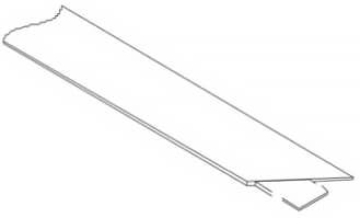
Fig. 7 Scheme I to solve the difficulty in positioning the bend line
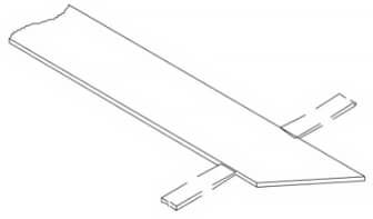
Fig. 8 Solution for difficult positioning of the bend line figure 2
Figure 9 shows the processing diagram of scheme 1. By adopting this scheme, the part can be well positioned.
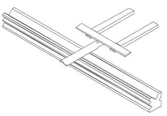
Fig. 9 Scheme I processing diagram
Figure 10 shows the processing schematic diagram of scheme 2. In this scheme, side plates are added on both sides of the workpiece, which can ensure that the processed part meets the design requirements.
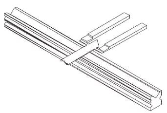
Fig. 10 Scheme II processing diagram
Solution for easy deformation of the part
According to Figure 11, the laser cutting machine shapes the part when its thickness is low.
It is worth mentioning that laser cutting falls into the category of fusion cutting, generating high temperatures.
However, in the case of the part structure represented in the figure, it may undergo deformation, resulting in inaccurate bending positioning. To avoid such problems, appropriate process measures must be taken.
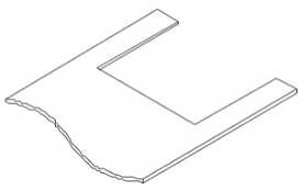
Fig. 11 Easily deformed structure
Solution: As shown in Fig. 12, for the large gap shown in the figure, the part is easy to deform during handling or positioning, resulting in inaccurate bending positioning.
Generally, the process elongation shown in the figure will be added.
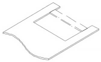
Fig. 12 Adding process stretchers
Incorporating stretchers into the notch can increase the overall rigidity of the part and prevent warping.
After the bending process is complete, use manual plasma to cut the stretchers.
For large and long pieces, it is necessary to retain the stretchers to avoid deformation during lifting or installation in the subsequent process. The stretchers should only be removed after welding in the next process.
Solution that the groove width of the part is too narrow to bend
As illustrated in Figure 13, the groove width of the workpiece is too narrow, causing it to interfere with the upper die during bending. This, in turn, leads to deformation of the part, which makes it impossible to complete processing, and the final size of the part does not meet the requirements specified in the drawing.
To solve this problem, we recommend the solution shown in Figure 14. Before bending the workpiece, it is advisable to reverse bend a certain angle in the middle of the workpiece. Afterwards, the part can be bent according to the drawing specifications.
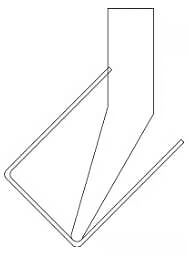
Fig. 13 Interference between the part and the upper die
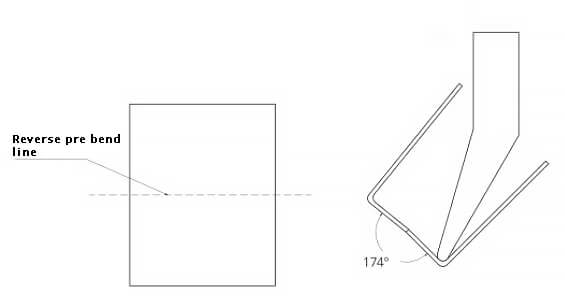
Fig. 14 After pre-bending, the upper die no longer interferes with the workpiece
After the workpiece is bent, press the pre-bent bend with a flattening die (Fig. 15) and ensure the flatness and size requirements of the workpiece.
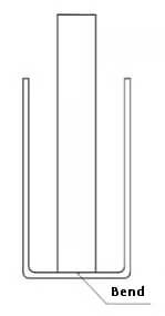
Fig. 15 Point pressure and flattening with flattening die in pre-bending
Solution to the problem of the workpiece being too long and the slot width being too narrow for bending
Based on Figure 16, the developed length measures 2500 mm, the groove width is 100 mm, and the leg height is 64 mm. These parameters are entered according to the process card requirements. To proceed, an upper die with R8 V60° and a height of 134mm is chosen, and a lower die with no. V07, with an opening of 35mm and a depth of 65mm.
Various bending deflection parameters are then entered and the workpiece is placed on the work table to perform the required bending. However, during the folding process, a problem arises. Because the upper die of the R8 gooseneck is thick and the gooseneck is very small, the first bending edge interferes with the mold when the one-sided bending of the second side is quick to reach 90°. This interference makes it impossible to guarantee the curvature angle.
Attempting to force bending can cause several problems, including deformation of the part, damage to the mold and non-conformity of the part size to the drawing.
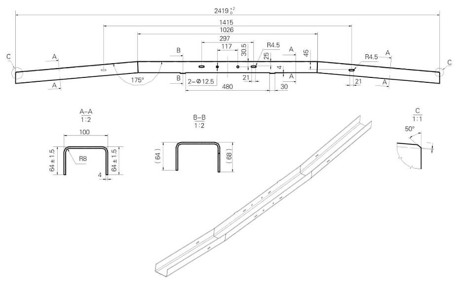
Fig. 16 Part groove width is too narrow to be bent
Solution for very long parts and very narrow channel width
After carrying out on-site research and studying the parameters of the machine tool, as well as observing the existing mold, we discovered that the gooseneck opening of the upper mold R6 is larger than necessary. However, after testing, we found that it meets the process requirements.
Following the above workflow, we performed synchronous operations without any interference between the mold and the part, which met the requirements.
After several adjustments to the Y-axis and X-axis parameters, the dimensions of each point on the part met the drawing requirements.
After identification, we confirm that it meets the process requirements.
Conclusion
Process stretching and anti-cracking grooves are indispensable in sheet metal bending and are crucial to ensuring part quality and processing efficiency.
It is worth noting that while ensuring product quality, it is also worth discussing the flexible application of process stretching and anti-cracking grooves along with reducing sheet metal waste rates.