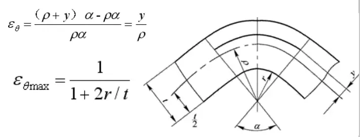
Definition of curvature
Bending refers to the processing method to bend the product into a certain angle and shape using a mold in press production.
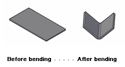
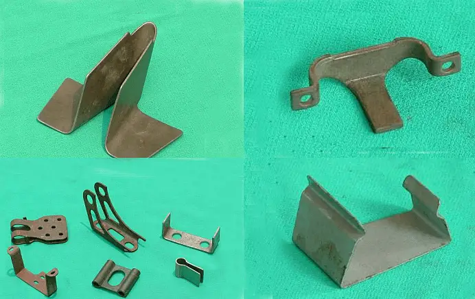
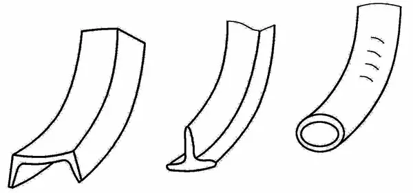
Bending example
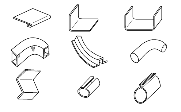
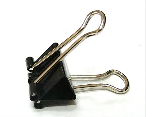
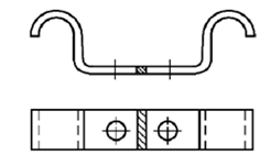
Doubled parts in life
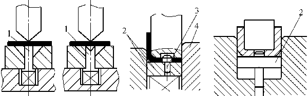
Forming Curved Parts with a Mold-1
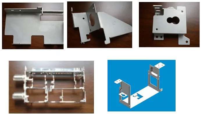
Forming bent parts with a die-2
The mold used for bending is called a bending mold
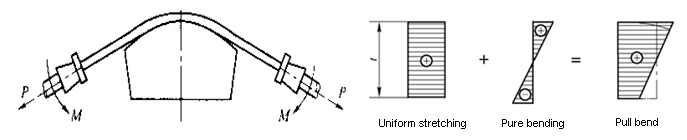
Analysis of the bending deformation process
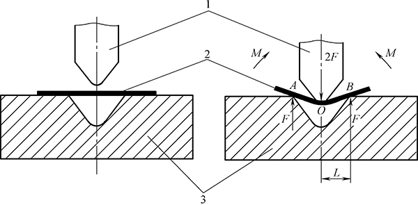
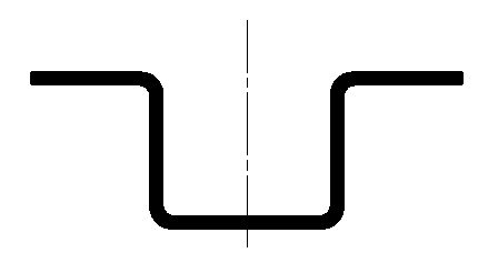
V-shaped bending process
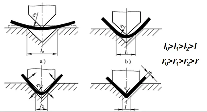
1.1 Flexion form
1.2 Bending deformation characteristics
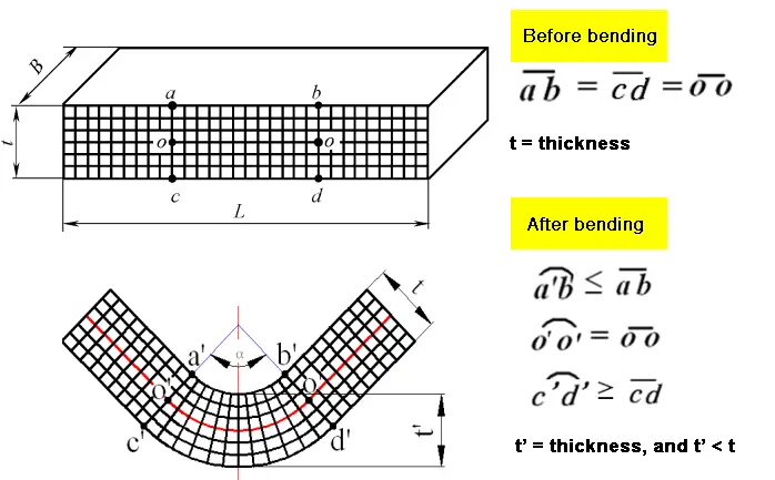
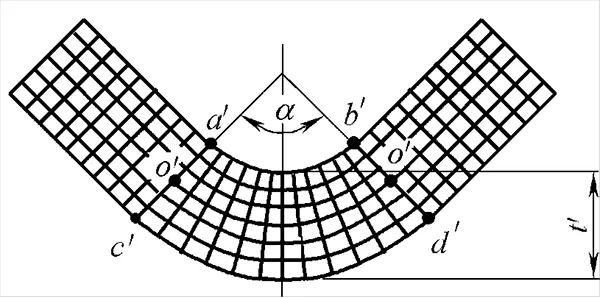
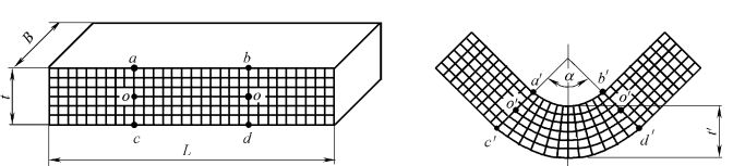
Curved blank cross section change
Deformation characteristics of the bending deformation zone:
- The piece is divided into two parts, straight edges and rounded corners. Deformation occurs mainly at rounded corners. Rounded corners are the main deformation area of bending deformation.
- The deformation zone is not uniformly deformed: the outer zone is stretched in the tangential direction; the inner zone is compressed in the tangential direction and a neutral stress layer appears – a layer of metal whose length does not change before and after deformation.
- The thickness of the deformation zone becomes thinner, η= t'/t≤1, and the degree of thinning is related to the size of r.
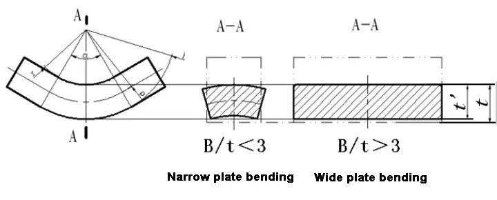
- Changes in cross-section: the wide plate remains unchanged, the inner area of the narrow plate becomes wider, and the outer area becomes narrower.
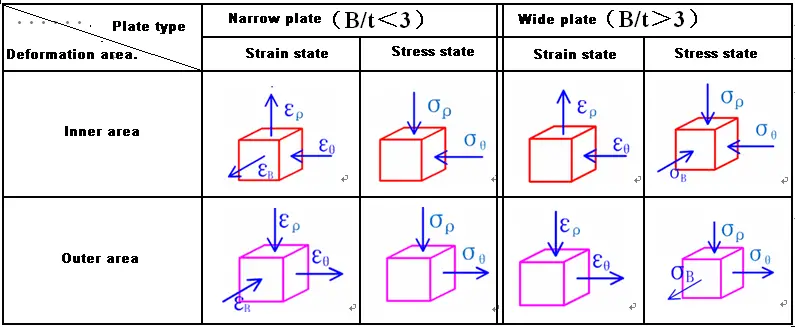
1.3 State of stress and deformation in the flexural deformation zone
Analysis and quality control of bent parts
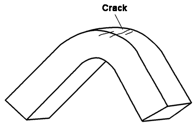
2.1 Bending crack
Flexural cracking is a phenomenon in which cracks occur in the outer layer of the material in the flexural deformation zone.
The main reason for the occurrence of bending cracks is that the degree of bending deformation exceeds the forming limit of the material being bent.
Flexural cracks can be avoided.
- Bending deformation
r/t —— Represents the degree of bending deformation.
The smaller r/t, the greater the degree of bending deformation, there is a minimum relative radius of curvature r min /t.
- Minimum relative bending radius and its influencing factors
The minimum relative bending radius refers to the relationship between the bending radius of the outermost fiber and the thickness of the sheet when the sheet is bent and almost cracks.
Factors affecting the minimum relative bending radius:
1) Mechanical properties of the material: good plasticity, small r min /t.
2) The grain direction of the sheet: the fold line is perpendicular to the grain direction, r min /t is small
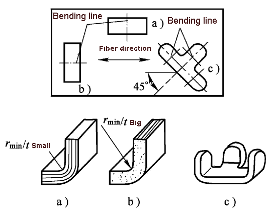
3) The surface and side quality of the sheet: the surface and side quality are good, r min /t is small
4) The sheet thickness is thin: r min /t is small
- Setting various parameters of the bending process:
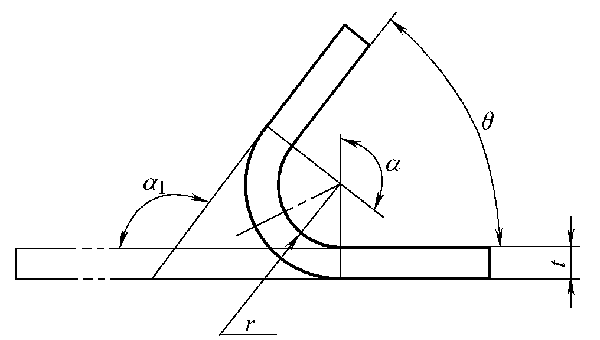
(1) The fillet radius r of the bending deformation area is called the bending radius.
(2) The r/t relationship between the radius of curvature and the thickness of the sheet is called the relative radius of curvature.
(3) The radius of curvature when the outermost fiber of the sheet is close to tearing during bending is called the minimum radius of curvature r min .
(4) The relationship between the minimum radius of curvature and the thickness of the sheet is called the minimum relative radius of curvature r min /t.
(5) The angle at which the part is bent, that is, the complementary angle α1 of the right angle of the part after bending, is called the bending angle.
(6) The diagonal angle α of the right angle between the bent parts is called the central bending angle.
(7) The angle θ of the straight side of the product after bending is called the angle of the bent part.
- Measures to control flexion
(1) Select a material with good plasticity for bending, and perform annealing treatment on the cold work hardened material before bending.
(2) Bending with r/t greater than r min /t is used.
(3) When arranging, make the fold line perpendicular to the direction of the fiber structure of the sheet.
(4) Direct the burr side to the bending punch side or remove the burr before bending. Avoid scratches, cracks and other defects on the outside of the curved part.
2.2 Recovery
Bending rebound refers to the phenomenon in which the shape and size of the bent part becomes inconsistent with the mold when it is removed from the mold, which is known as rebound or springback.
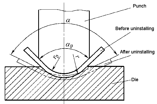
The reason for rebound is that the total deformation during plastic bending is composed of two parts: plastic deformation and elastic deformation. When the external load is removed, plastic deformation remains and elastic deformation disappears completely.
- Recovery form
(1) The radius of curvature changes from rp during loading to r during unloading
(2) Changing the angle of the bent part, the amount of change:
Δα=α-α P
When Δα> 0, it is called positive rebound
When Δα<0, it is called negative rebound
- Factors affecting recovery
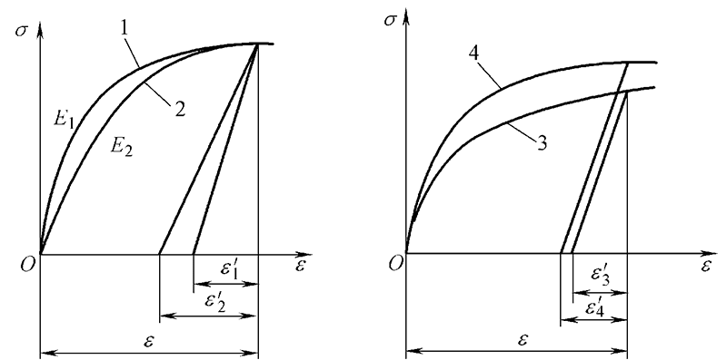
1) Mechanical properties of the material: The higher the yield point and the higher the hardening index, the greater the elastic return; the higher the modulus of elasticity, the lower the elastic return.
2) The greater the relative curvature radius, the greater the bounce.
3) The greater the central bending angle, the greater the length of the deformation zone and the greater the springback accumulation value, so the springback will increase.
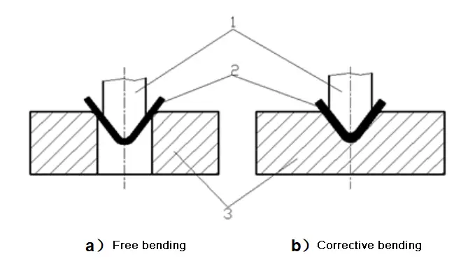
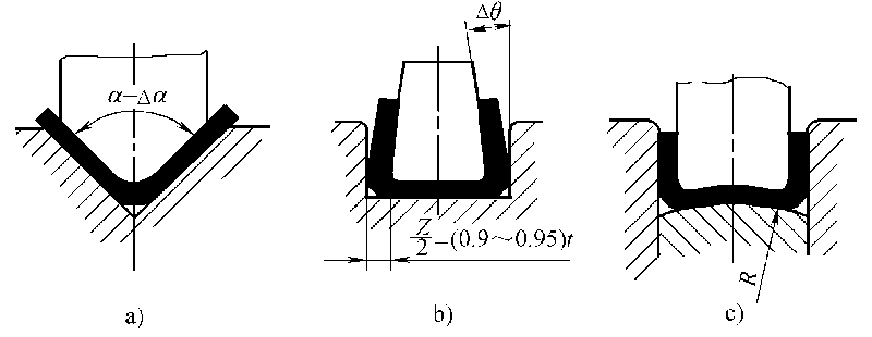
4) Bending method: The springback of correction bending is greatly reduced compared with free bending.
5) Part shape: The more complicated the shape, the greater the angle of a bend and the lower the elastic return.
6) Mold structure: The springback of the bottom die is small.
- Measures to reduce recovery
(1) Improve the design of bent parts and select appropriate materials
1) Avoid choosing a very large r/t.
2) Try to use a sheet with a small yield point, a small hardening index and a large modulus of elasticity for bending.
(2) Adopt a suitable bending process to change the stress-strain state of the deformation zone.
1) Use corrective flexion instead of free flexion.
2) Using the bending process
3) The material for cold hardening should be annealed first to reduce the yield point σs. For materials with high rebound, hot bending can be used if necessary.
(3) Reasonably design the bending die
1) Compensation method
2) Make the mold on partial protrusions
3) Soft mold method
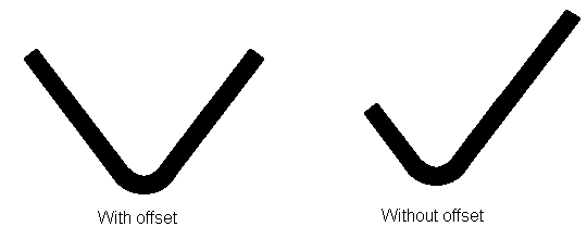
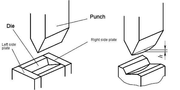
2.3 Displacement
Offset refers to the phenomenon of the blank moving in the mold during the bending process.
As a result of the displacement, the length of the two straight sides of the bent part does not meet the drawing requirements, so the displacement must be eliminated.
- Reasons for compensation
(1) The shape of the blank of the bent part is asymmetrical to the left and right.
(2) The positioning of the blank is unstable and the pressure effect is not ideal.
(3) The mold structure is asymmetrical to the left and right.
- Measures to control displacement
1) Choose a reliable positioning and pressing method and use a suitable mold structure
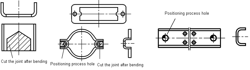
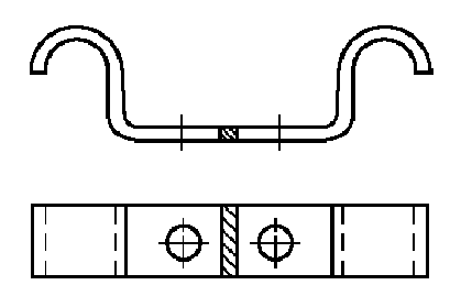
2) For small asymmetrical bent parts, the process of paired bending and then cutting should be adopted
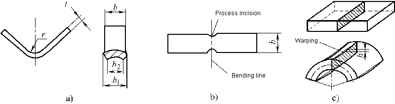
2.4 Distortion and warping of sheet metal cross-sections
2.5 The deformation zone becomes thinner and the length of the bent part increases
This makes it difficult to accurately determine the size of the blank.
The bending die design step is to design the bending die first and then the molding die.
Calculation of the bending process
3.1 Calculation of the blank size of the bent part
- Position of the neutral deformation layer
Neutral stress layer refers to a metal layer with a constant length before and after bending deformation or a metal layer with zero tangential deformation in a region of bending deformation.
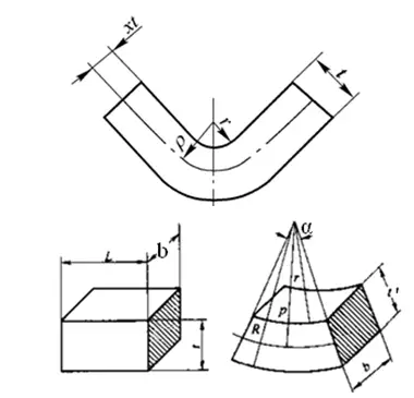
Equal volume before and after bending: Lbt=π(R 2 -r 2 )bα/2π
Simplified: ρ=(r+ηt/2)η
Abbreviated as: ρ=r+χt
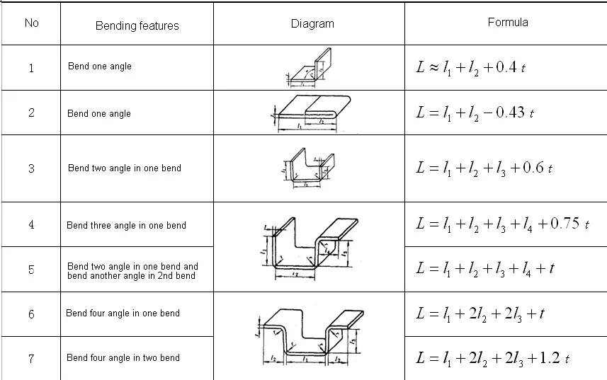
2. Calculation of the length of the blank of the bent part
(1) Bending parts with fillet radius r> 0.5t
1) Starting from one end of the folded piece, divide it into several straight and circular segments.
2) Find the neutral layer displacement coefficient χ according to Table 4-3.
3) Determine the radius of curvature ρ of the neutral layer of each arc segment according to formula (4-3)
4) According to the radius of curvature ρ1, ρ2 of each neutral layer and the corresponding central angles of curvature α1, α2…, calculate the length of each arc segment ll, l2… l i =πρ i α i /180°
5) Calculate the total length of expansion L = a + b + c +… + l 1 + l 2 + l 3 +…
(2) Curves with fillet radius r <0.5t – empirical formula
Example of calculating the unfolded length of a curved part
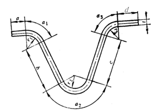
Example 4-1 Fold the part shown in Figure 4-30 and try to calculate its unfolded length.
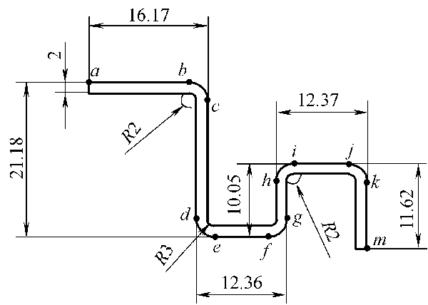
Solution: (1) The workpiece is divided into straight line segments l ab l cd l ef l ah l jj l kilometers and arc segments l bc l d l fg l hi l prank from point a.
(2) Calculate the extended length of the arc segment.
For arcs l BC i hi i jest : R = 2mm, t = 2mm, then r/t = 2/2 = 1, and if χ = 0.3 is found in Table 4-3, then:
Arc length l BC = I hi = I jest = (2土0.3 × 2) × π/2 = 4.082 (mm)
For arc l of l fg : R = 3 mm, t = 2 mm, then r/t = 3/2 = 1.5. According to Table 4-3, χ= 0.36, so:
Arc length l = L fg = (2 ± 0.36 × 2) × π/ 2 = 5.84 (mm)
(3) Calculate the total length of the folded blank:
l = ∑/ l straight edge + ∑l rounded corner = l ab + l cd + l ef + l ah + l l j + l kilometers + l aC + l de + l fg + l hi + l jest
= 16.17-4 + 21.18-9 + 12.36-10 + 10.05-9 + 12.37-8 + 11.62-4 + 3 × 4.802 + 2 × 5.84 = 65.836 mm
3.2 Calculation of the force of the bending process
- Calculation of bending force
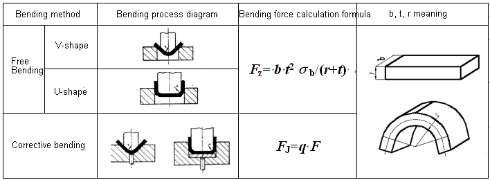
Calculation of pressure force or ejection force
- Pressure force: F S =C S F Z
- Ejection force: F D =C D F Z
- Determination of nominal press pressure
For free bending with pressing, the selection of press tonnage needs to consider the bending force and pressing force, i.e.:
F press ≥1.2(Fz+F S )
For bending correction, only the bending force correction can be considered when selecting the press tonnage, i.e.:
F press ≥1.2F J.
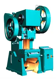
Press selection example
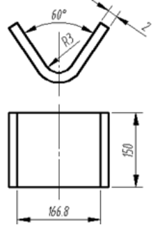
Example 4-2 Bend the V-shaped piece shown in Figure 4-32. The known material is steel 20 and the tensile strength is 400 MPa. Try to calculate the free bending and correct the bending force respectively. When using the press device, try to select the press tonnage.
Solution: From the formula in Table 4-6:
When freely folding: F Z = b * t 2 σ b / (r + t) = 150 × 2 × 2 × 400 / (3 + 2) = 48,000 (N)
F S =C S F Z = 0.4 × 48,000 = 19,200 (N)
Then the total process power is: F Z +F S = 48,000 + 19,200 = 67.2 (KN) then the equipment tonnage: F press ≥ 1.2 (F Z +F S ) = 1.2 × 67, 2 = 80.64 (KN).
When the bending is corrected, q can be taken as 50MPa in Table 4-7 and can be obtained from the formula in Table 4-6:
F J. = q * A = 50 × 166.8 × 150 = 1251 (KN)
Then the tonnage of the equipment: F press ≥ 1.2*F J. = 1.2 × 1251 = 1501.2 (KN).
Bending Process Design
4.1 Analysis of the bending process
The manufacturability of the bent part refers to whether the shape, size, precision, materials and technical requirements of the bent part meet the technological requirements of the bending process, that is, the adaptability of the bent part to the bending process – a requirement from a product design perspective.
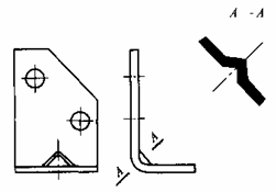
- Shape Requirements for Curved Parts
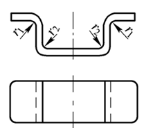
(1) To avoid displacement during bending, it is necessary that the shape and size of the bent part are as symmetrical as possible.
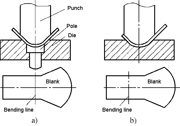
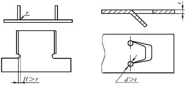
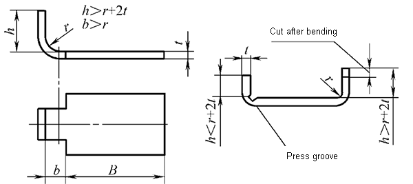
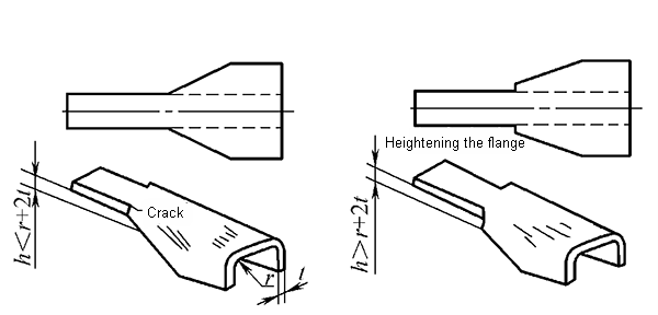
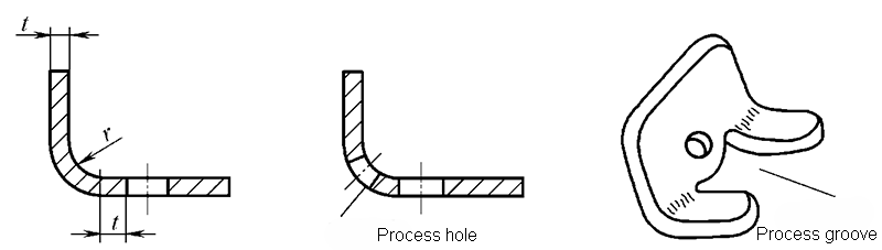
(2) When folding a section of the edge locally, to avoid tearing the root of the fold, a groove must be cut between the folded part and the unfolded part or the process hole must be drilled before folding
(3) Add connecting strips and positioning process holes.
2. Dimensional requirements for bent parts
(1) The bending radius should not be less than the minimum bending radius.
(2) The height of the straight side of the curved part must meet: h> r + 2t
(3) The distance between the hole edge of the bent part must meet the following requirements:
- Accuracy requirements for bent parts
The dimensional tolerance of bent parts shall be in accordance with GB/T13914-2002,
Angle tolerance in accordance with GB/T13915-2002,
The unmarked position tolerance complies with GB/T13916-2002,
Limit deviation of dimensions without tolerances is in accordance with GB/T15055-2007
- Material Requirements for Curved Parts
The material of the bent part must have good plasticity, a small yield ratio and a large modulus of elasticity
- Requirements for sizing
4.2 Process arrangement of bent parts
1) Simple curved parts: single bending. Bending parts with complex shapes: Two or more bending shapes.
2) Bending parts with large batch size and small size: Use progressive die or composite die as much as possible.
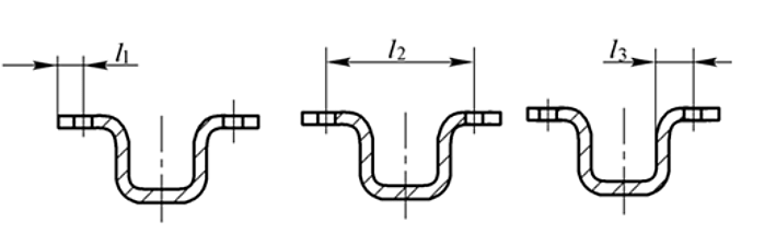
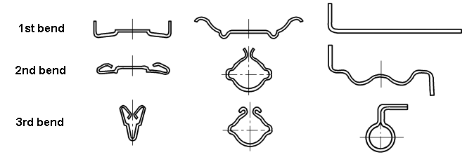
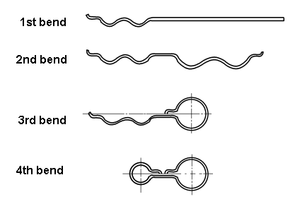
3) When multiple folds are required: fold both ends first and then fold the middle part. The previous turn must take into account the reliable positioning of the last turn.
4) When the shape of the folded piece is not symmetrical: fold as much as possible and then cut.
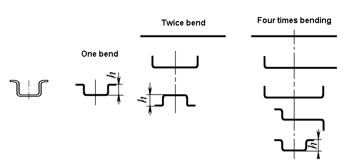
Process arrangement of typical bent parts
A curve
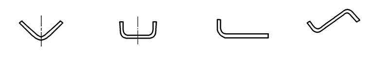
Fold twice
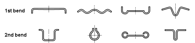
Triple curvature
Four curves
Flexible arrangement of flexible parts
- Workpiece shape
- Accuracy Requirements
- batch size
Bending Mold Design
5.1 Bending mold type and structure
According to the degree of process combination, the bending die can be divided into:
- Single Process Bending Die
- Composite Bending Matrix
- Progressive Bending Matrix
According to the shape of the part, the bending die can be divided into:
- V-shaped bending die
- L-shaped bending die
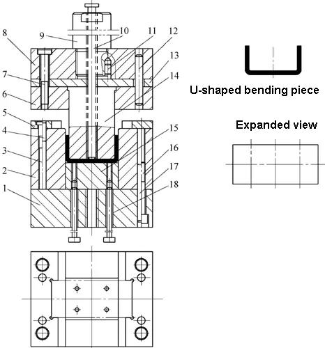
- U-shaped bending die
- Quadrilateral flexion matrix
- Z-shaped bending die
- Round Bending Die
- Bending mold for hinge
- …
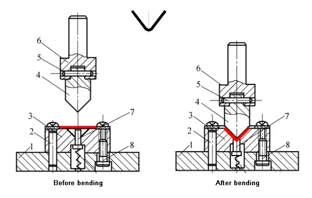
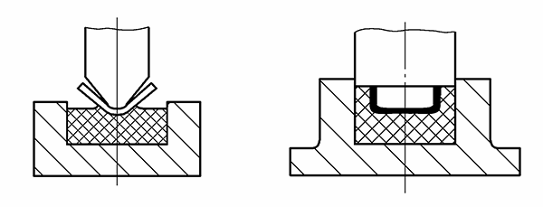
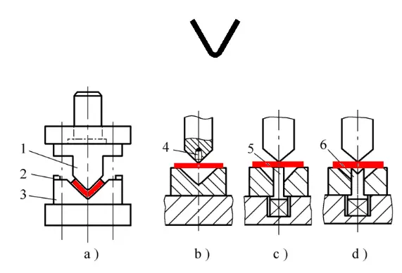
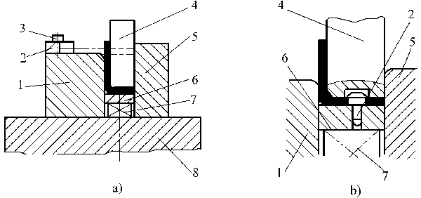
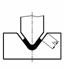
- V-shaped bending die
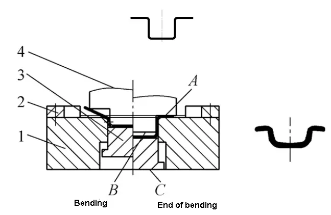
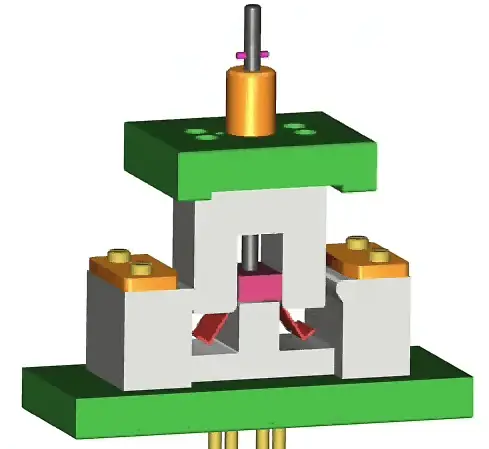
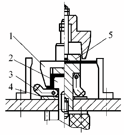
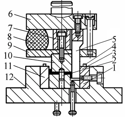
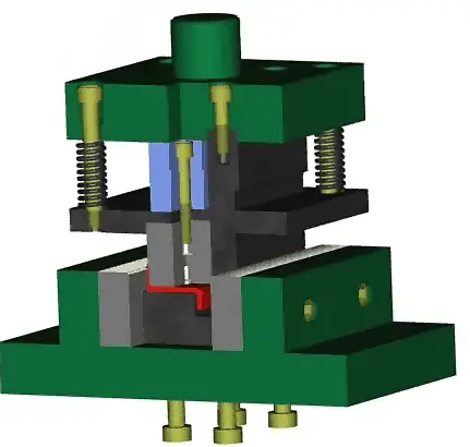
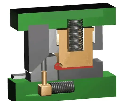
V-Shaped Precision Bending Die
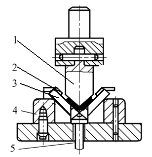
- 1- punch
- 2-position plate
- 3-move die
- 4- support plate
- 5- ejector
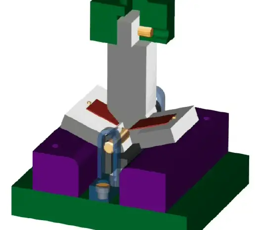
V-Shaped Precision Bending Die
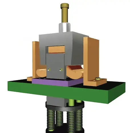
- L-shaped bending die
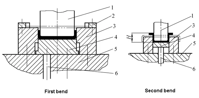
3. U-shaped bending die
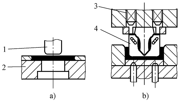
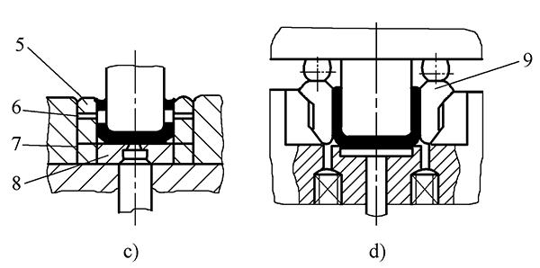
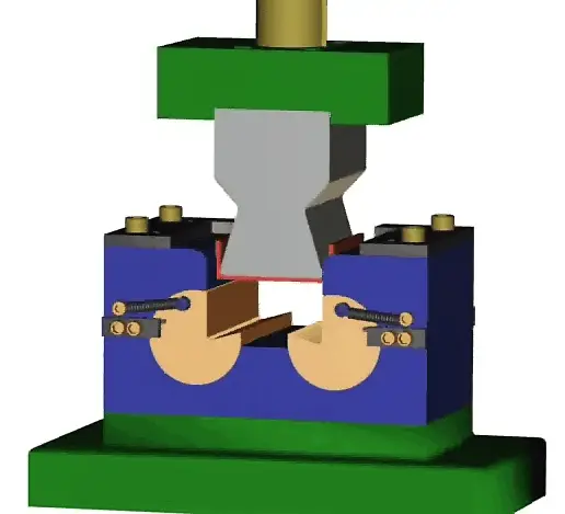
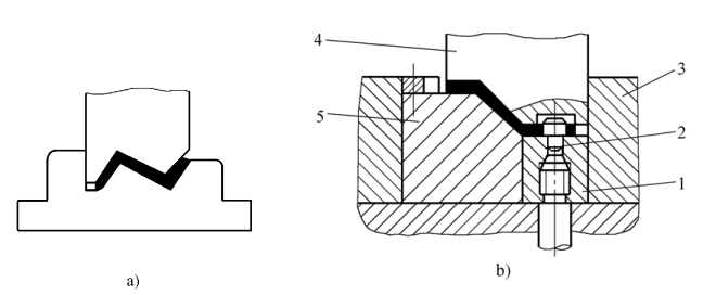
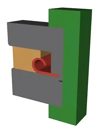
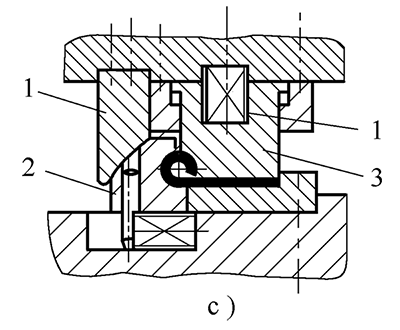
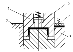
Bending die for closed angle parts
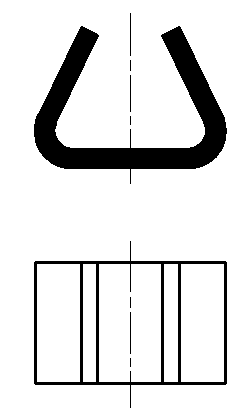
Closed Angle Bending Die-1
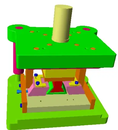
Closed Angle Bending Die-2
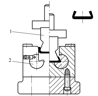
1 male die 2 rotating female die 3 springs
4. Quadrilateral flexion matrix
Quadrilateral Forming One-Time Bending Mold
Bending die for quadrilateral forming twice
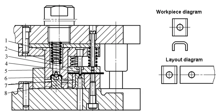
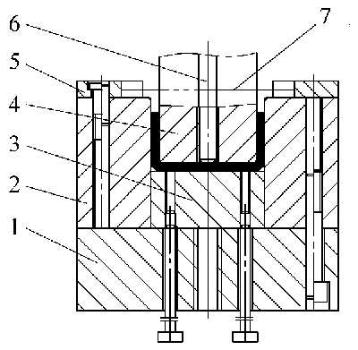
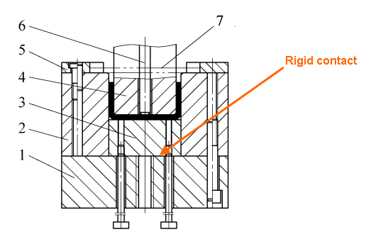
Compound Bending Matrix for Quadrilateral
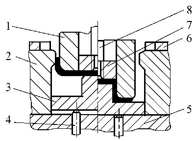
- 1-Concave and concave matrix
- 2-Woman dies
- 3-Punch in motion
- 4-Ejector
- 5-Bottom mold base
- 6-position plate
- 7-pulse block
- 8-Handle
Compound Bending Matrix for Quadrilateral
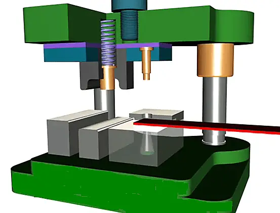
Quadrilateral flexion mold with pendulum
- 1-Die
- Punch 2 furniture
- Block of 3 pendulums
- 4-Support plate
- Block 5-pusher
Concave Die Oscillating Quadrilateral Bending Die
- Z-shaped bending die
Z-Shaped Single Bending Die
Bending die for bending Z-shaped parts in two steps
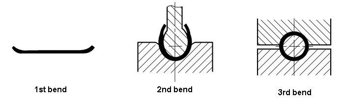
- Round Bending Die
Round fold and double fold
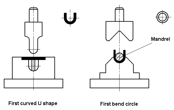
Round bending die-a curve
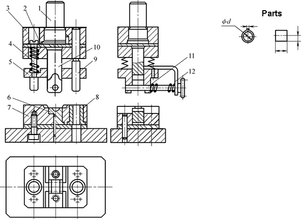
Single bend forming die for circular part with rotating die
- 1- support
- 2 punches
- 3 balance die
- 4-ejector board
Single Bending Forming Die for Large Round Parts with Oscillating Die
Two processes bending a great circle
Three steps bending a big circle
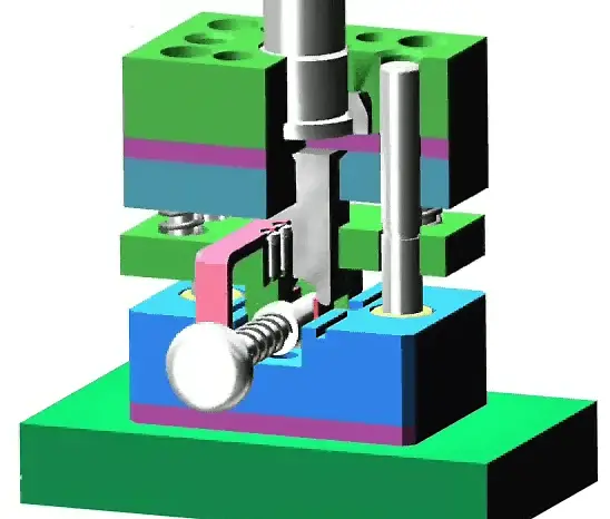
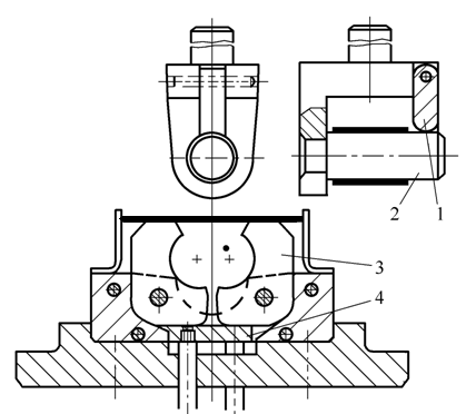
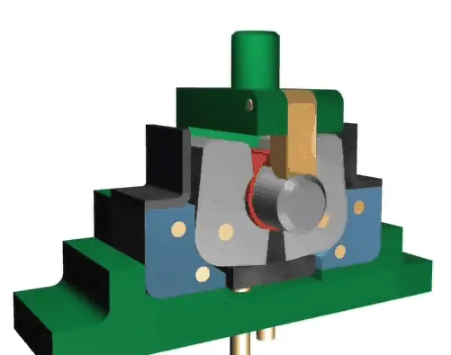
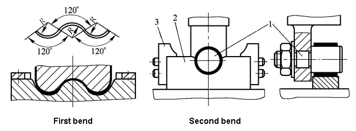
- Bending mold for hinge
Hinge Part Double Bending Die
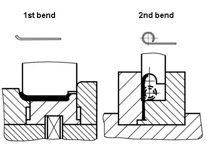
Hinge Part Single Bending Die
- Other bending dies
(1) Composite cutting and bending mold
(2) Progressive bending die
5.2 Bending mold part design
- Workpiece design
(1) Punch fillet radius
(2) Die fillet radius
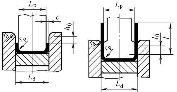
(3) Die depth
(4) Convex and concave die clearance
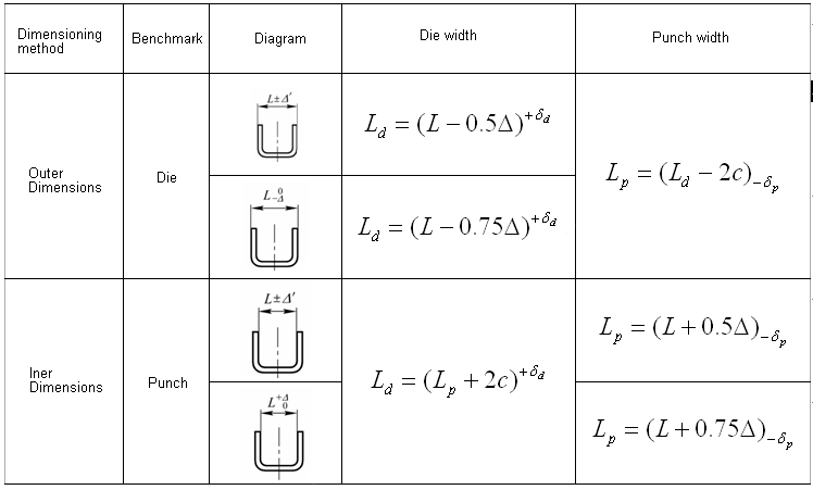
(5) Width of U-shaped convex and concave die

(1) Punch fillet radius
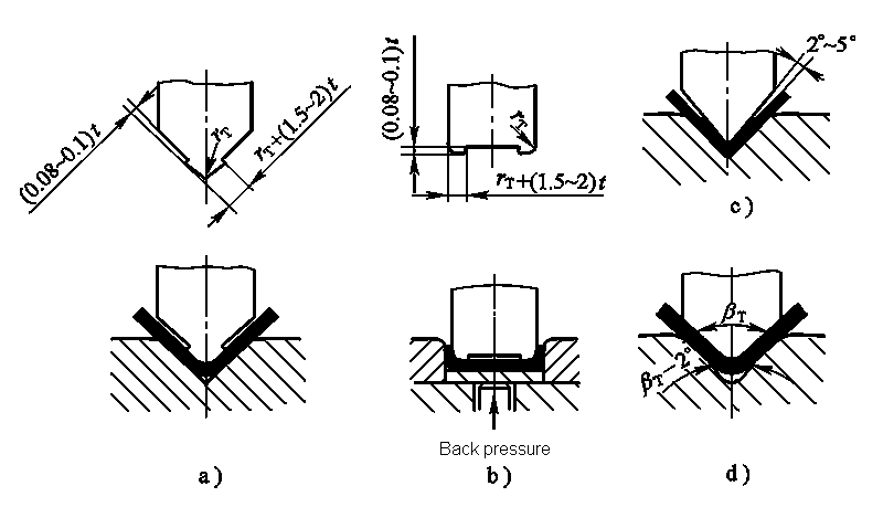
1) When r≥r min take r p = r, where r min is the minimum radius of curvature allowed by the material.
2) When r
3) When r/t > 10, the springback must be considered and the punch fillet radius must be corrected.
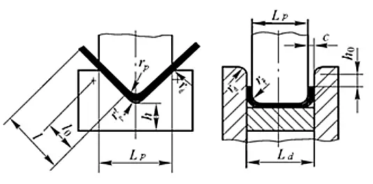
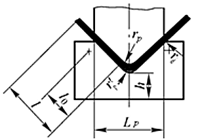
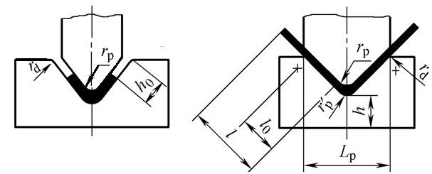
4) The bottom part of the V-shaped bending die can be opened or retracted with groove or fillet radius: r' p = (0.6-0.8) (r p + t).
(2) Die fillet radius
The size of the corner radius of the die affects the bending strength, the service life of the bending die, and the quality of the part bent during the bending process.
- When t≤2mm, r d = (3-6)t
- When t = 2-4 mm, r d = (2-3) t
- When t> 4 mm, r d = 2t
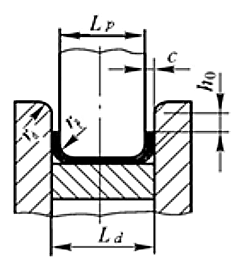
(3)Depth of die
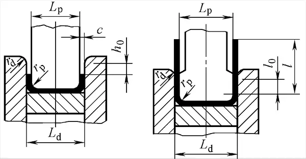
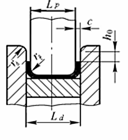
(4) Clearance of convex and concave matrix c
The size of the gap between the male and female die affects the bending force, the service life of the bending die and the quality of the bent part.
- Steel plate c=(05~1.15)t
- Non-ferrous metals c = (1 ~ 1.1)t
When the precision of the bent part is high, the gap value should be reduced accordingly and c = t can be obtained.
The die gap of the V-shaped bent part does not need to be designed. It can be achieved by adjusting the closing height of the press.
(5)Width of U-shaped convex and concave curved die
2.Design of positioning parts
Since the blank fed into the bending die is a single piece, the positioning parts used in the bending die are positioning plates or pins.
3.Design of pressing, unloading and feeding parts
4.Fixed parts design
Including: die handle, upper die seat, lower die seat, guide post, guide sleeve, backing plate, fixing plate, screws, pins, etc., refer to the blind die design.
4 types of metal stamping process
- Metal Stamping and Die Design: Suppression
- Metal stamping and die design: bending
- Metal Stamping and Die Design: Deep Stamping
- Metal Stamping and Die Design: Forming