1. Dimensioning part drawings
1. Rationality of part dimensions
2. Methods and steps for part sizing
3. Sizing Precautions
Basic requirements for dimensioning in part drawings
The dimensions on the part drawing must be marked in accordance with the standard, complete, clear and reasonable.
Requirements for reasonable sizing:
(1) Meet design requirements to ensure machine quality,
(2) Meet process requirements to facilitate manufacturing and structural inspection.
To meet these requirements, we must master certain practical production knowledge and relevant professional knowledge.
1. Rationality of part dimensions
The dimensions in the part drawing must not only meet the requirements of accuracy, completeness and clarity, but also make the dimensions reasonable.
Definition of the rationality of dimensions in the part design:
- Meet project requirements and ensure the service performance of components;
- Meet the requirements of processing technology and make processing and measurement convenient;
- Low cost.
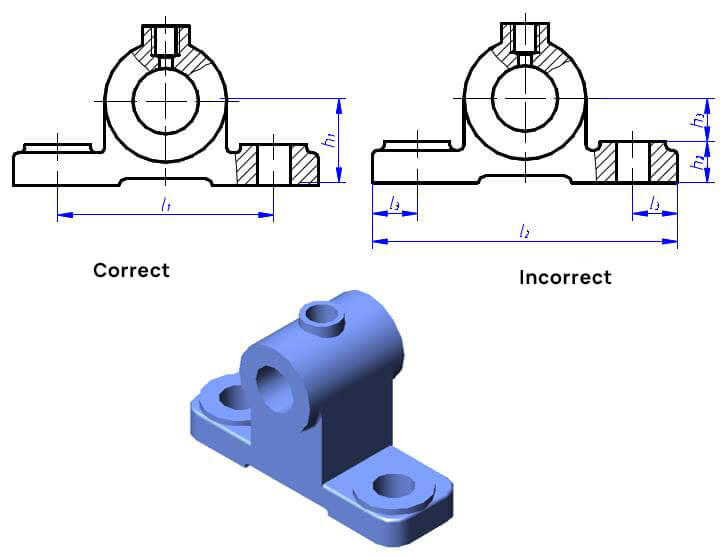
Whether the dimensions are reasonable or not, the key points are as follows:
- Distinguish the primary and secondary dimensions of parts;
- Select the appropriate dimensional tolerance;
- Select the dimension data correctly.
1. Main and non-main dimensions
Main dimensions:
Dimensions that affect the specification and performance of components or machines, such as mating dimensions, dimensions for determining the exact position of parts in components, connecting dimensions, installation dimensions, and dimensions that affect the interchangeability and working accuracy of parts.
Non-main dimensions:
Such as outer contour dimension, non-suitable dimension, dimension used to meet the mechanical properties, structural shape and process requirements of parts, etc.
The main dimensions must be indicated directly:
two). Set size
The marked dimensions are convenient for measurement and inspection.
It is not necessary to write down all the dimensions of the parts on the assembly drawing.
It is only necessary to better describe the performance, working principle, mounting relationship and required dimensions of the machine.
1. Specifications and dimensions
Also known as performance dimension, it reflects the specifications and operating performance of components or machines.
This dimension must be determined first in the project. It is the basis for designing, understanding and selecting machines.

2. Mounting dimensions
Dimensions that indicate the assembly relationship and working accuracy between parts generally include the following:
1. Assembly dimensions refer to some important dimensions with assembly requirements between parts.
2. The relative position dimension indicates the important distance and clearance between parts to be guaranteed during assembly.
3. Machining dimensions during assembly. Some parts can only be machined after they have been assembled. The machining dimensions during assembly must be marked on the assembly drawing.

3. Installation Dimension
The dimensions that need to be determined to install the components on the machine or the machine on the foundation.

4 . Overall dimension
Indicates the total length, width and height of the machine or part.
It allows for the dimensions required for packaging, transportation, installation and plant design.

5 . Other important dimensions
It does not belong to the above dimensions, but the dimension must be guaranteed during design or assembly.