
What is the difference between accessory and support? They are often used together. However, despite the similar purpose, they are not interchangeable. By examining how they are used to improve manufacturing quality, reduce production costs, and automate work, we can better understand the subtle differences between different manufacturing technologies.
Innovative manufacturing concepts such as lean production system, cellular manufacturing, single-minute die changeover and cycle time analysis have been introduced into the production process. These innovative approaches require a variety of effective and cost-effective instruments and workpiece holders. Read on to learn more about the difference between jig and assembly.
What is a device?
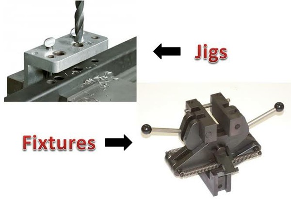
Jigs are tools used to hold and position the part during the production process and to guide cutting tools.
In other words, a fixture holds the part and guides the tool to increase the repeatability, accuracy and productivity of the parts produced.
A drilling jig is a common example of a template. It guides the drill bit as it drills holes in the desired locations. Using drilling jigs significantly increases production speed.
Device types
Device types are listed below.
1. Model theory

The simplest model is the stencil device. The plate with two holes serves as a template for the workpiece to be processed and is fixed to it. The holes in the template serve as guides for the drill, and the holes in the workpiece are drilled in the same relative positions as the holes in the template.
2. Plate meter

The angle plate gauge is used to improve the model gauge. Holes are added to the model surface. With the plate gauge, accurate hole spacing can be maintained when drilling solid components.
3. Channel Model

A channel gauge has a cross section that resembles a channel. By turning the knurled knob, the component is positioned and secured in the channel. The drill bushing serves as a guide for the instrument.
4. Diameter gauge

Drilling radial holes in a cylindrical or spherical part can be done using a diameter gauge.
5. Foil Stencil

Loading and unloading can be done using a blade on the device.
6. Touch device

A ring gauge is used to drill holes in circular flange parts. Holes are made by passing the tool through the drill bushings while the workpiece is firmly attached to the drill body.
7. Cash Template

This type of fixture features a box-shaped design that holds the part in place so it can be drilled or machined at different angles at the same time.
What is a device?
Jigs are used in manufacturing tools that allow the automation of the production process. When it comes to automated industrial processes, you will hardly find one without devices. Devices that hold and guide cars during the welding and assembly process.
For example, this is necessary for assembly line production of automobiles. To check the quality of manufacturing processes, they can also be used to hold a product in place while it is inspected with optical or laser scanning. It's almost impossible to walk through a factory without encountering some kind of device.
Device types
1. Rotating device

Lathes have typical clamping devices such as mandrels and manifolds between the center and on mandrels or faceplates, which facilitate the clamping of normal parts. However, holding unusually shaped components can be a challenge.
Simple and unusually shaped workpieces can also be clamped in four-jaw chucks or with soft-shaped jaws. In contrast, workpieces with complex shapes must be held in place using rotating devices. The workpieces are held in place by these devices, which are usually attached to the spindle tip or a faceplate.
2. Milling device

The workpieces are held in place by milling devices, usually attached to the spindle tip or a faceplate. The table is moved and positioned in relation to the cutter to achieve the desired results. Before starting the process, the parts are placed on the device base and secured.
3. Compensation device

These devices are used on a variety of different types of broaching machines to position, hold, and support workpieces during operations such as broaching keyways and holes. Cleaning internal draft holes using a clamping plate as a device.
4. Grinding device
Grinders use a variety of devices to position, hold and support workpieces during grinding. Work holding devices such as chucks, chucks and the like can be used in conjunction with these devices.
5. Drilling Jig
The construction of this device does not need to be as robust as milling devices because it is never subjected to the same severe cutting loads as milling devices.
6. Indexing device

Various components need to be machined on different surfaces so that their machined surfaces or shapes are evenly distributed. To produce as many surfaces as possible, these elements must be indexed as frequently as possible. A suitable indexing mechanism is built into the retention devices (devices or brackets). An indexing device is a device that contains a device that can be used to index data.
7. Thread cutting device
For cutting internal threads in drilled holes, thread cutting jigs are designed to hold and stabilize identical workpieces. Irregularly shaped and unbalanced parts always require the use of special fixtures, especially when thread cutting is required for mass production.
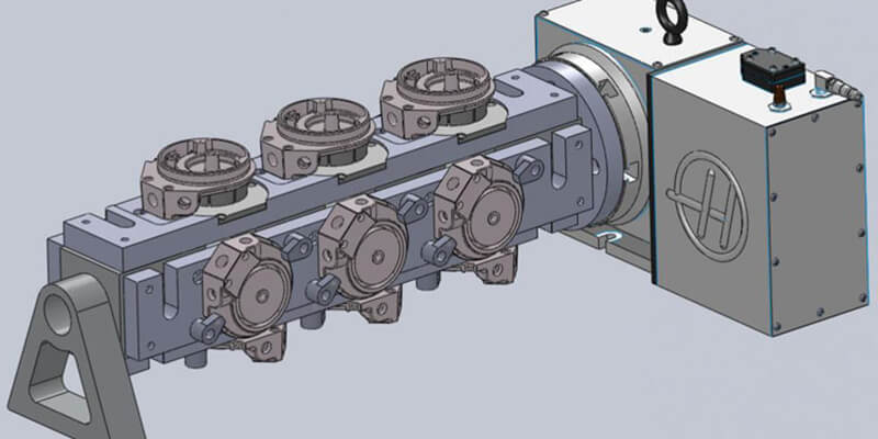
8. Duplex device
A duplex device is a device that contains two identical components at the same time and allows them to be processed simultaneously on two different stations.
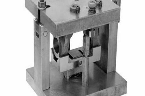
9. Welding device
Welding fixtures are designed to prevent welded structures from deforming during the process as they hold and support the various components. The fixture must be light but firm, and the fixture pieces must be placed far enough away from the welding area for it to work. To withstand the forces during welding, the device must be extremely stable and rigid.
10. Mounting device
The purpose of these accessories is to keep the various parts of the assembly in their correct relative position.
Templates vs. assemblies: what's the difference?
Jig vs. support, what's the difference? There are two main instruments used in mass production processes: jigs and fixtures. It is common for the two names to be mistakenly used as synonyms when they actually fulfill different functions.
Jigs guide the cutting tool to a specific, predetermined location on the workpiece. A workpiece is supported and positioned using fixtures. Unlike a jig, jigs do not clamp the tool to the workpiece.
Compared to jigs, jigs are more compact and require less weight to remain stable under high cutting and vibration loads. Unlike jigs, jigs can be held or clamped to a table depending on the task and do not require additional tools.
Why are jigs and fixtures important in CNC machining?
Careful selection of fixtures and fittings significantly improves the economics of the manufacturing process, enabling smooth operations, simplified production and rapid process transition. Jigs and fixtures help compensate for the limitations of the CNC machine when machining a part. They are designed to ensure secure clamping and maintain the reliability of the part position during the machining process. Below we describe the different functions of tools and accessories for custom CNC machining:
1. Parts inventory
The main purpose of jigs and fixtures is to ensure secure fixation of the part during the machining process. They are individually adapted to the respective part to be processed. They provide custom part clamping when a part needs to be clamped at a specific angle or clamped into a specific shape.
Reliable, customized fixtures are essential to avoid unwanted inaccuracies caused by vibration and tool pull. Some examples of devices used as part holders include lathes, chucks, center drills, milling jigs, and various fixture plates.
2. Protection of parts
One function of jigs and fixtures is to protect the part during machining. They are a great help in maintaining the desired surface quality and correct concentricity.
Bushing devices, bushings and caps are generally developed for special parts where the surface finish is controlled. This is done to protect the surface of the finished part from metal chipping/abrasion from various workpiece machining processes. Additionally, customer-specific machining centers are specifically designed to machine special parts with strict overall concentricity specifications.
3. Site control/foolproof
Jigs and fixtures are very important to maintain dimensional and positional accuracy. They keep the part in the right place and in the correct orientation during the machining process. For these reasons, equipment is a practical way to make a process foolproof to minimize errors due to human factors.
Fixtures control position, orientation and stability by restricting the degrees of freedom in the workpiece. This is done through the use of pins, clamps, levels and fixing material in constructing the required device. Levels provide support for the part, clamps allow for adjustable mounting and disassembly, and pins provide precise position control for specific features.
When machining special parts, features such as holes and slots are controlled in a specific location where machining may be difficult due to some mounting limitations. For this reason devices are developed. Jigs are the most reliable method for machining difficult parts.
4. Consistency of parts
Jigs allow various custom parts to be machined while maintaining their quality. They ensure that the quality remains the same from piece to piece. Examples of feature controls that require consistency include flatness, parallelism, and perpendicularity.
5. Configure markdown
Jigs are a great way to eliminate the tedious inspection process when loading a part. A fixture designed for a specific part makes the entire CNC process a plug-and-play operation. The operator's job partially consists of just loading the workpiece, as all necessary location control and part reference are already managed in the fixture. Many CNC machining shops do this in their processes to save valuable setup time for other value-added processes. Some examples of accessories that reduce setup time include One Minute Die Change (SMED) accessories, milling accessories, soft jaws, hex milling accessories, and more.
Basic Methods and Steps for Making Jigs and Brackets
Pre-design preparation of initial fixtures and fixture design information, including the following.
(1) Design note, finished part diagram, raw part diagram and process flow as well as other technical information.
Understand the processing technology requirements of each process, the positioning and clamping program, the processing content of the previous process, the situation of the blank, the lathe used in processing, tools, checking gauges, machining tolerance and quantity of cutting, etc.
(2) Familiarize yourself with the production batch and the need for jigs and fixtures. Determine approximately how many accessories and brackets you will need.
(3) Understand the main technical parameters of the lathe used, its performance, specifications, accuracy and structure of the device connecting part, contact size, etc.
(4) The inventory of device materials and support. The following materials are used to produce fittings and brackets: hardened steel, gray cast iron, plastic, carbide, epoxy resins, stainless steel, bronze, low melting point steel alloys. You can choose the right material according to your processing project.
Consideration of design of devices and supports
Jig and fixture designs often have a single structure, which gives the impression that the structure is not very complex, especially now that the hydraulic device is in fashion, greatly simplifying its original mechanical structure. However, if the design process is not considered in detail, it will inevitably lead to unnecessary problems. Therefore, the following points should be taken into consideration when designing devices and accessories.
(1) The blank tolerance of the machined part. If the size of the white space is too large, it will cause interference. So, make sure you prepare a blank drawing before designing. Leave enough space.
(2) Removing chips from the device goes smoothly. Due to the limited machining space of the machine tool, jigs and fixtures are often designed to be more compact. This is often ignored when machining creates chips at the fixture's dead end.
Another problem is that the chip flow may not be smooth, which causes major problems during further machining. Therefore, at the beginning of the process itself, problems that arise in the editing process must be taken into account. Ultimately, the device and support are intended to improve efficiency and facilitate operation.
(3) The general opening of the device and bracket. If the opening is neglected, the operator will have difficulty loading the map, which is time-consuming and tedious.
(4) The basic theoretical principle of device and support design. Each set of jigs and fixtures must undergo numerous tensioning and loosening operations to meet the user's needs from the start.
The fixture and fixture must remain accurate, so don't design anything that violates the principle. Even if you can get away with it now, it won't be sustainable in the long run. Good design must stand the test of time.
(5) The interchangeability of positioning elements. The positioning elements are subject to intense wear. Therefore, a quick and easy replacement should be considered. It's best not to build larger pieces.