The press brake is mainly used to bend metal sheets in a straight line. Sheet metal can be formed into various geometric shapes through the use of a simple die and processing equipment, as well as by stretching, stamping, punching and corrugated pressing.
In practical production, the press brake is mainly used to bend metal cabinets, boxes, U-beams and rectangles with various geometric shapes. This process has several advantages, such as high bending straightness, absence of teeth marks, no peeling and no wrinkles.
With the continuous advancement of CNC press brake manufacturing technology, it has become more and more popular among sheet metal manufacturing companies due to its high positioning accuracy, convenience, flexible disturbance compensation and consistent processed products.
However, optimizing the utilization of the press brake to maximize its functions and benefits remains an urgent issue for CNC press brake manufacturers in limited circumstances.
Over time, we have effectively expanded the functionality of the press brake and accumulated experience through adding auxiliary tools and modifying existing dies, as well as through flexible application on the job site.
This article, using the AMADA HFT170 numerical control press brake as an example, provides a complete guide to its use and techniques.
1. Add auxiliary tools
To use the machine tool flexibly and easily, it is essential to incorporate auxiliary tools. Adding auxiliary tools not only expands the machine's processing capabilities but also increases its processing efficiency.
1) Transition plate (fast die auxiliary intermediate plate)
The opening height of a press brake refers to the distance between the upper and lower work tables. The HFT170 numerical control press brake features a large opening height, which allows for an expanded processing range.
As illustrated in Figure 1, adding a transition plate to the original plate can increase the bending height of the component side by 85 mm, enabling deep bending processing with a higher bending edge.
The width of the custom transition plate can be adjusted to fit the size of commonly used parts, making it ideal for small width components with high curvature edges on both sides.
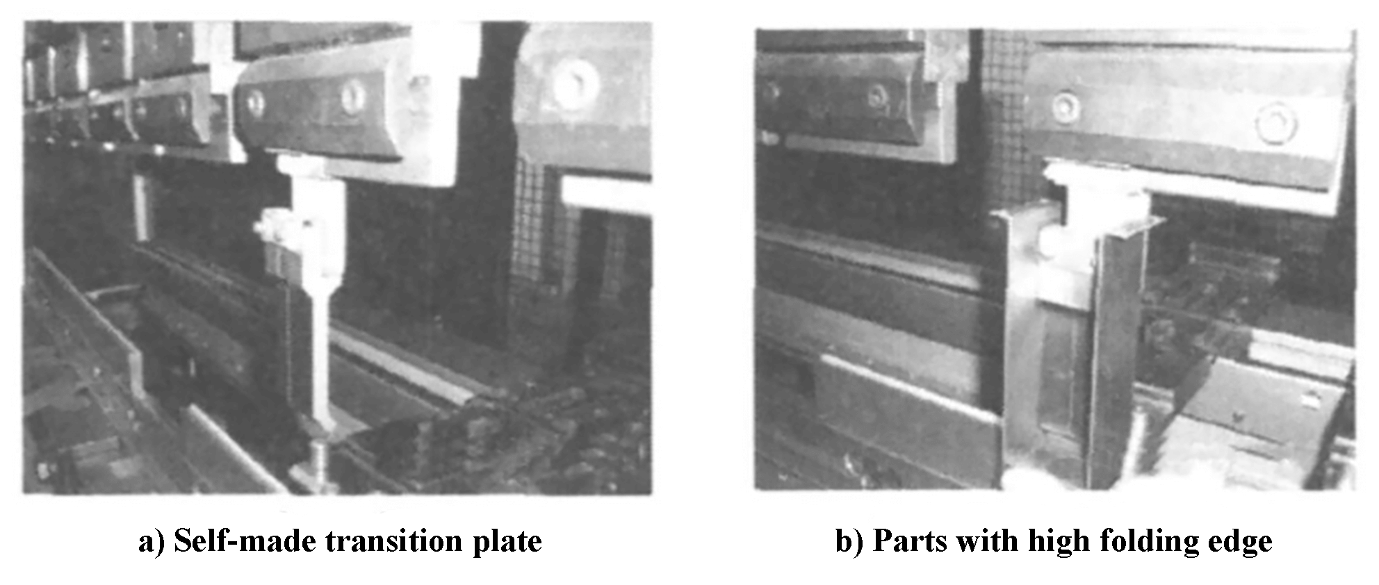
Fig. 1 Self-made transition plate and parts with high folding edge
2) Front seat angle
As shown in Figure 2, an angled bench was installed at the front of the machine to hold small parts, reducing the time needed to retrieve them. Additionally, a small work table has been added to facilitate the processing and collection of small parts.
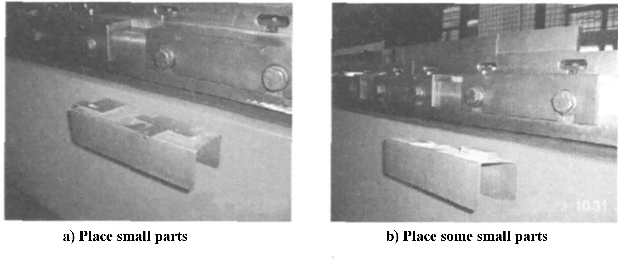
Fig. 2 Front seat angle
two . M make the most of the data
The effectiveness of a press brake largely depends on the upper and lower dies. If the number of dies is limited, the processing range of the machine tool is severely restricted.
Therefore, within fixed conditions, optimizing the combination and localized transformation of existing dies to maximize their function is a challenge that all machine tool users must consider.
The following section will provide an introduction on how to expand the function of a CNC press brake through die changes.
1) Tip of the upper matrix R
Over time, the tip of the upper die may wear unevenly, causing changes in its height and affecting bending accuracy. To solve this problem, the tip of the die can be ground and corrected to have a consistent R shape, in combination with a large V-shaped groove. This allows thick sheets to be bent, extending the life of the die.
2) Replace the discarded matrix to perform leveling
If there is no composite bending die, the pressed dead edge formation problem needs to be solved. Pressed dead edge is a folded shape with two overlapping layers, commonly used for reinforcement. This type of edge is rare on plates with a diameter greater than 2.0 mm.
Typically, the pressing dead edge is formed through a composite bending die that requires at least two processes. Figure 3 illustrates the common method of using a composite bending die. In the first step, the material is bent at a 30° angle and in the second step, the 30° bend is placed in front of the composite die and subsequently pressed into the pressed dead edge shape.
However, in this case, there is no composite bending die available. The only die that exists is a 30° acute bending die. The first step of the composite bending process can be achieved using this die. However, the second step requires a workaround.
One solution to the second step is to use the top and bottom of the array as the top and bottom planes. The top die needs to be flattened, which can be achieved by removing the existing top scrap and grinding the knife edge into a flat style. This will solve the problem of pressed dead edge formation.
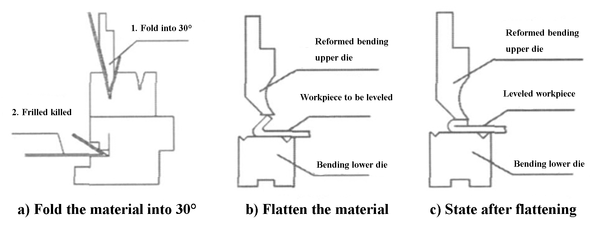
Fig. 3 Hemming and flattening process
The modified matrix can be flattened for use. However, during actual processing, machine operators can sometimes make mistakes such as reversing the folded edge or having uneven fold sizes. Unfortunately, when part surface requirements are not high, parts may have to be discarded.
Although it is possible to level just the bent edge, it is difficult to do so. However, using a combination of upper and lower dies makes it easier to obtain a flat surface. By pressing parts manually into the upper and lower dies and using a CNC press brake, parts can be flattened efficiently.
3. Technique is in operation
1) Bending material placement and die processing
When planning, the following factors should be considered to minimize die replacement time and frequency:
The. Grouping of materials of the same thickness;
B. Arrange matrices of the same type together;
w. Placing similarly shaped matrices together.
By following these guidelines, the time and effort required for die replacement can be reduced.
2) Right-angle positioning of narrow and small parts
Positioning can be challenging when the folded part is narrow and long. During the process, it is common to use a gauge for positioning, but this can result in the bent part tilting. To resolve this, the method shown in Figure 4 can be employed. In this method, the die is firmly fixed to the lower die to ensure a right angle and prevent tilting during bending.
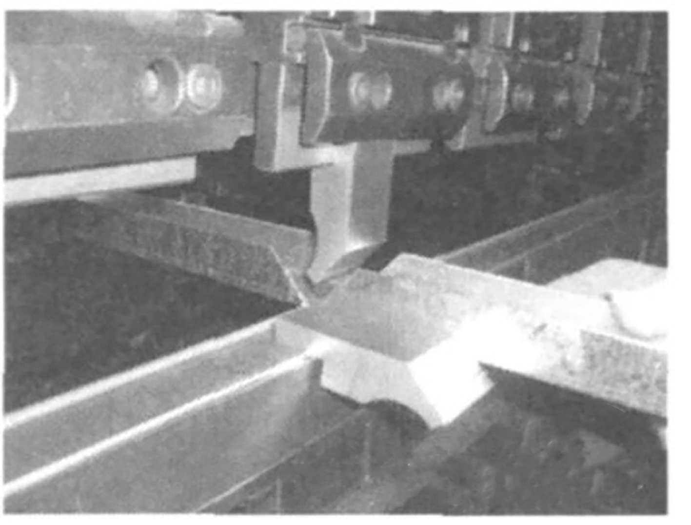
Fig. 4 Processing method of right angle positioning in narrow parts
3) Bending of triangular pieces
Bending parts with sharp edges can be difficult to get close to the back of the gauge. The minimum size L is normally less than or equal to 10 mm, immediately after the fixed gauge, and requires the use of positioning devices. Neglecting this step of the project and process during actual work can often result in such problems.
The choice of bending die depends on the size of the parts. A single-piece die is used for small parts, while a parallel-pair die is used for double parts.
4) Add R sheet
Customers may have different requirements for the R-value on the same bending edge. During the machining process, for parts that do not require high dimensional accuracy, the base plate can be used to increase the R-value to meet the required specifications after bending.
To determine the required R value, the plate thickness is selected based on the relationship between V and internal R and is then bent into the shape shown in Figure 5. During use, the upper die is secured with a clamp. This method is easy to use and can be applied to multiple layers.

Fig.5 Folded shape
5) Single part with multi-die configuration
We used the HFTI70 press brake with two hydraulic cylinders and employed the multi-die configuration as illustrated in Figure 6.
This configuration allows us to simultaneously install the upper and lower dies of the same model, allowing us to perform multiple bending processes across the entire part, thus reducing the time required for die installation and repetitive part handling.
Currently, the market has introduced equal height bending top dies, where the height of the top die is standardized.
Additionally, multiple mold formats can be used on the same worktable, allowing us to segment and bend different dies, resulting in a single die installation and a single parts transport.
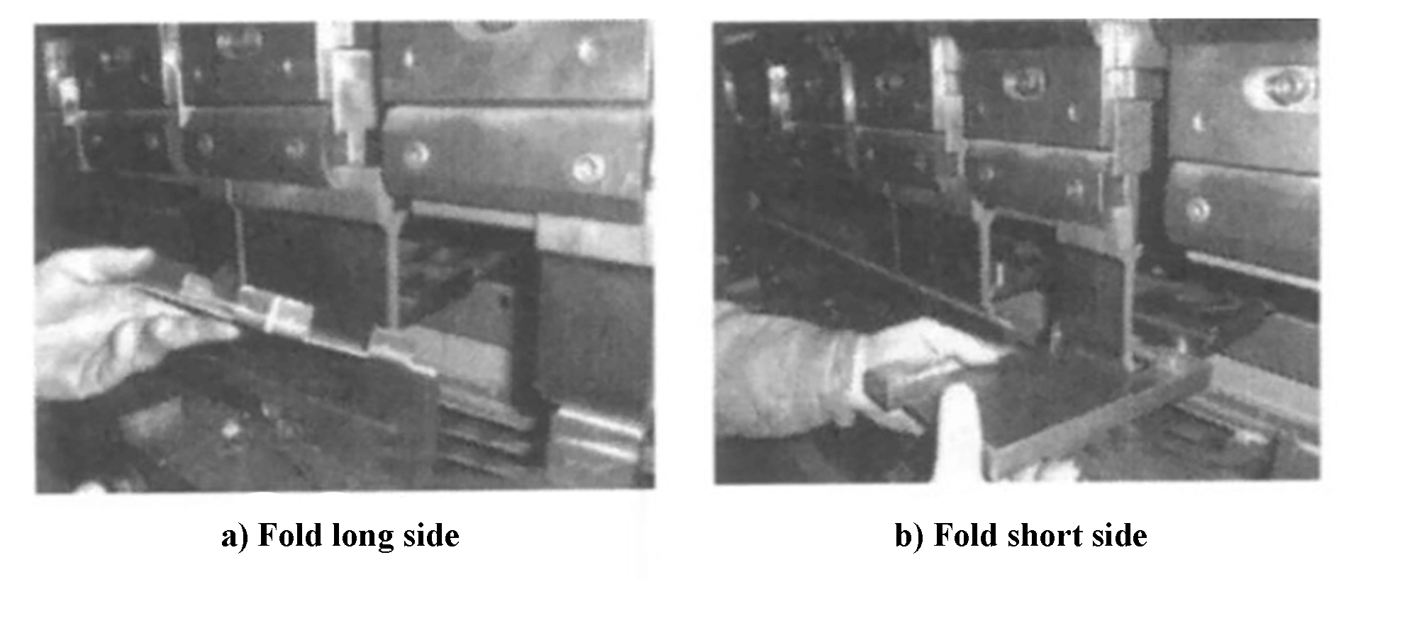
Fig. 6 Multiple array configuration
6) Typical parts program record
After processing typical parts, it is important to record the processing parameters in a timely manner and store the program in the storage area of the press brake together with the part drawing number.
This way, the program can be easily reused in the future, significantly reducing the time required for preparatory work before folding.
We also maintain a table that contains detailed information such as part name, drawing number, figure, material and bending parameters.
The table is organized by material type, including steel sheet, aluminum sheet, and stainless steel sheet, and each type is further differentiated by material thickness, making it easy to find typical parts.
When combined with the process cards, this table serves as a comprehensive machining guide, allowing even inexperienced workers to follow the part processing steps.
7) The length of the die is not enough to fold into sections
In on-site processing, the die length is often less than the bending edge due to the use of specific dies designed for specific products.
When the length of the die is shorter than the bending edge, we use a segmented bending method.
At the point where the length of the die is close to the folded edge, it is perpendicular to the fold of the folded edge, and then the folded edge is folded into the desired size into segments.
Figure 7a illustrates the folded part on the left side and Figure 7b represents the folded part on the right side.
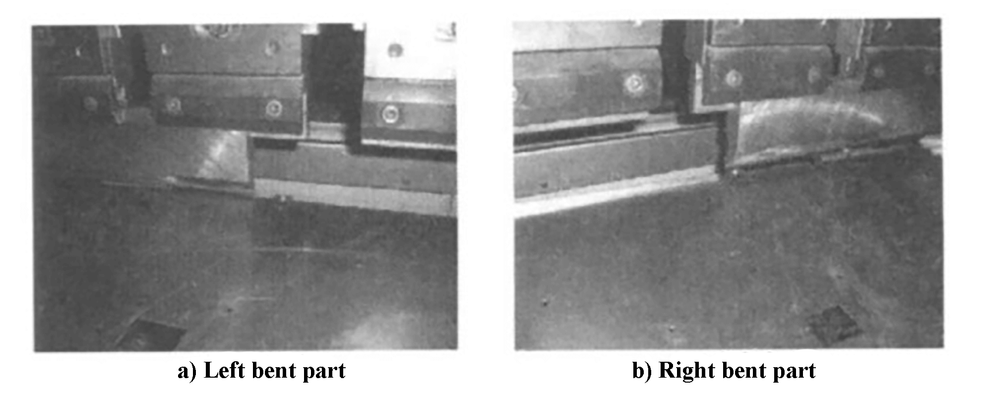
Fig.7 Folding parts
8) Position with the pin on the rear gauge
When the size of the bent workpiece is large, it often results in the workpiece sinking due to its weight and the short, portable workpiece, making it difficult for the operator to hold the workpiece in place.
To ensure parts are level, an operator must be positioned at the back gauge to hold parts in a horizontal position by hand. This requires the presence of two operators during processing.
During work, it was discovered that the rear gauge can be lowered to a certain extent and the rear gauge pin can be used for positioning.
By placing parts horizontally on the back gauge, not only the number of operators is reduced, but the accuracy of the machining process is also effectively maintained.
9) Bending deep size closed shape parts
In actual processing, flexible use of deep-sized closed-shape parts can be achieved through bending.
Without using a closed deep bending die, when bending the parts as shown in Figure 7, we adopt the clamping state depicted in Figure 8 to separate the transition plates. The spacing is slightly greater than the width of the pieces, allowing two pieces to be folded at the same time with a reasonable dimensional distribution.
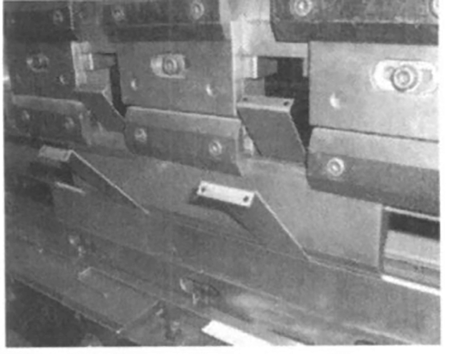
Fig. 8 Clamping status
4. Conclusion
The processing methods and techniques described above have effectively addressed the processing challenges faced in producing a large number of similar parts in the company's products.
They are highly suited to the current trend of producing multiple varieties in small batches with a short production cycle.
Through years of production experience, these techniques have not only reduced tooling expenses, but also shortened the production and processing cycle, reducing production costs and improving product quality.
These machining methods and techniques can also be applied to CNC press brakes with similar structure.