Schedule
1. Familiarization with common and specialized matrix formats:
Knowing the available matrices makes programming more convenient and efficient.
2. Rational application of gaps in the matrix:
Previously, standard clearances were 0.1 times the plate thickness for aluminum and copper, 0.15 times for iron, and 0.2 times for stainless steel. Now, AMADA proposes a new die clearance standard for hydraulic punching machines (all three presses in our factory are hydraulic).
The die gap can be appropriately increased by 0.05 times the plate thickness based on the original standard.
This is because hydraulic punch presses have a slower instantaneous cutting speed and increasing the die gap will not affect the appearance of the cut section, while also preventing the material from bouncing during the cutting process.
3. Die cutting quantity:
During the cutting layout process, it is essential to calculate the cutting amount of each die stroke. Generally, the length of the material cut by the die should not be less than 2/3 of the length of the die; otherwise there may be leftovers.
Rectangular shapes are prone to debris, particularly at the four right angles, while circular shapes are the least likely to have debris. Therefore, it is essential to pay attention to the punching sequence during the cutting layout process.

In the example above, Figure 1 shows that drilling first the circular shape and then the square shape can easily cause cracks in the four corners of the square shape. If the punching sequence is changed to that in Figure 2, die wear will be much less.
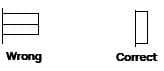
During the cutting layout process, it is essential to use the longest edge of the matrix to cut the edges, as shown in the following example:
4. Length calculation in programming:
(1) In true line cutting:
When cutting edges continuously, the machine's own internal program will calculate this edge by dividing the total length of the cut edge minus the length of the first cut, instead of the total length divided by the length of the blade as we might imagine.
It is essential to note that when the punch press continuously cuts edges, it does not accurately connect each cut to the next. Instead, the punch press automatically defaults to a 0.2mm overlap between the two cuts. We must pay attention to this when calculating.
For example, when cutting a 240mm edge with a RE80x5 rectangular blade, we might think that exactly three cuts are needed.
However, if true line cutting is used, four cuts will actually be made, which significantly affects die wear and service life.
There are two solutions to this: first, we can use a single-blade approach, cutting one at a time; second, based on the actual situation, we can leave a knot of 0.4mm in the first cut.
(2) Nibbling:
Not all round or square dies can be used for nibbling. In our factory, we use φ10, φ11, φ12 round dies and RE6x3 square dies for nibbling. It is better not to use other dies for nibbling, especially smaller ones. Cutting is only suitable for thin sheets, as it causes rapid wear on the dies when used on thick sheets.
When using a round die to cut a circle, first pierce the center with a larger round die and then proceed with cutting. Don't leave any knots. When nibbling with a square die, it is best to leave three smaller, evenly spaced knots along the circumference.
5. Coming out of knots
During the programming process, nodes should not be made too big or too small; Furthermore, they should not be left too much or too little. If the knots are too large, the product will be difficult to remove or will be deformed after removal. If the knots are too small, the product may fall out.
What is the most appropriate size for us?
There is no set standard; depends on the actual situation. The ideal knot size is one in which the product does not fall during the punching process and becomes detached from the material due to its weight when the operator pulls the sheet from the work table.
Here are some benchmarks for your consideration:
| Metals | <1.0 | 1.0-1.6 | 1.6-2.5 | 2.5-3.0 | ||||
|---|---|---|---|---|---|---|---|---|
| corner nodes | Intermediate nodes | corner nodes | Intermediate nodes | corner nodes | Intermediate nodes | corner nodes | Intermediate nodes | |
| Aluminum, Copper | 0.35 | 0.4 | 0.4 | 0.5 | 0.5 | 0.5 | 0.5 | 0.6 |
| Iron | 0.3 | 0.4 | 0.4 | 0.4 | 0.4 | 0.5 | 0.4 | 0.5 |
| Stainless steel | 0.3 | 0.35 | 0.3 | 0.35 | 0.4 | 0.4 | 0.4 | 0.4 |
The above values are some reference values for leaving knots in common plate thicknesses, but the actual values depend on the specific situation. As for how many knots are appropriate, generally we should leave one knot between every 350-400mm. For example, if there is an unfolded rectangular diagram of 50x1200mm, we can divide it into three sections and leave two nodes in the middle. Try to leave knots symmetrically in the product to keep the stress balanced.
Note: During the composition process, nodes must be added appropriately at certain points.
Composition
Put different products of the same material and board thickness into a single sheet for one-time processing to achieve material, time and effort savings.
- Familiarize yourself with material specifications:
- Aluminum plate: t(thickness) * 1220*2440
- Copper plate: t(thickness) * 600*1500
- Cold plate (SPC): t(thickness) * 1250*2500 (t(thickness) * 1220*2440)
- Pickled board (SPHC/SPHD): t(thickness) * 1250*2500 (t(thickness) * 1220*2440)
- Electrolytic plate: t(thickness) * 1220*2440
- Stainless steel plate: t (thickness) * 1220 * 2440
These are some common specifications of sheet materials. Custom specifications can be requested based on unfolded product size requirements.
- Safety Zone: Pay attention to the safety zone while composing. Generally, the cutting edge of station D is set to 15 80, and the cutting edge of station E is set to 20 110. Do not include the die within the safety zone to avoid damaging the die and clamp.
- Distance between layouts: During composition, the minimum distance between products must not be less than the width of the matrix. For example, using RE45*5 for cutting, the minimum distance should not be less than 5mm.
- Shared edge composition: The AP100 has automatic shared edge command, but it can also be done manually. When composing with shared edges, be sure to increase the size of the nodes or leave more.
- Selection of matrices in typesetting: Use as few matrices as possible in typesetting. In the punching sequence, the last cutting die must be punched from the opposite side of the clamp towards the clamp.
- Special forming die punching: For forming dies such as flanging, semi-drawing, louvering and bridge pressing, pay special attention to the punching sequence. If forming downwards, leave larger knots and place the forming die last in the sequence, punching from the clamp toward the other side along the X direction and outward. If forming upwards, ensure that subsequent dies do not press into the forming position so that they do not need to be placed last in the sequence.
Common Problems in Programming Composition
There are several common problems in programming typesetting:
- Recording:
a) Material itself: For soft and light materials such as aluminum plates, embossing can easily occur during the punching process. Due to the light weight of the aluminum plate, the cutting waste itself is very light at the same punching speed, and when the waste has not yet fallen completely, it is lifted by the upper die and embossing occurs when the waste is pressed into the plate during the next cut.
b) Punching speed: During the cutting process, if the speed is too fast and the waste has not yet fallen completely, the upper die lifts the waste and embossing occurs when the waste is pressed into the plate during the next cut.
c) Insufficient cutting amount: During the punching process, if the cutting amount is less than 2/3, the die may lift the waste.
- Drag material:
a) Insufficient depth of the upper die: If the material is not completely drilled, the upper die is likely to drag the material when lifted.
b) Excessive die gap: If the lower die gap is too small, it is easy to pinch the material and the plate is likely to drag the material during movement.
c) Die cutting edge not sharp: If the material is not completely drilled, the upper die is likely to drag the material when lifted.
d) Press punching speed: If the speed is too fast and the material is not completely cut or dropped, it may cause the material to be dragged.
e) Insufficient ejection force: The spring pressure is not sufficient.
f) Misaligned punch, uneven distribution of forces.
- Residual dies:
a) Insufficient cutting amount: When it is less than 2/3 of the die length, residual die may occur.
b) During erosion, if the step is too small, severe residual death is likely to occur. Adjust the tone accordingly according to actual requirements.
- Product falling:
a) Nodes are too small, few, or not reasonably positioned.
- Half drawing shift and scratches:
When the plate moves, the half design gets scratched on the knife disc. When the half design moves on the knife disc, it gets stuck in the lower die. When the plate moves, the half design is forcibly dragged, causing material displacement and causing other half designs to be displaced.
To avoid these problems, consider the factors that cause them and take into account scheduling and on-site operations to resolve issues more quickly and accurately.