Currently, the global economy is practically entering a recession and the manufacturing industry is severely affected.
As part of the manufacturing industry, the steel sheet industry faces intense market competition in this economic climate.
Quality is crucial for industrial companies to thrive in this intense competition. In many sheet metal manufacturing processes, bending is a crucial step that has a major impact on the quality of the final product.
Therefore, controlling the bending accuracy and stability is of great importance to improve the quality of sheet metal parts.
Ways of Part Failure
In the production process, the following problems may arise:
When a new die is used to bend sheet metal parts in the press brake, the parts initially meet the specifications described in the drawing.
However, after a period of production, it is discovered that the parts bent with the same die no longer meet the specifications described in the drawing. This is mainly evidenced by two shapes, shown in Figure 1a and Figure 1b.
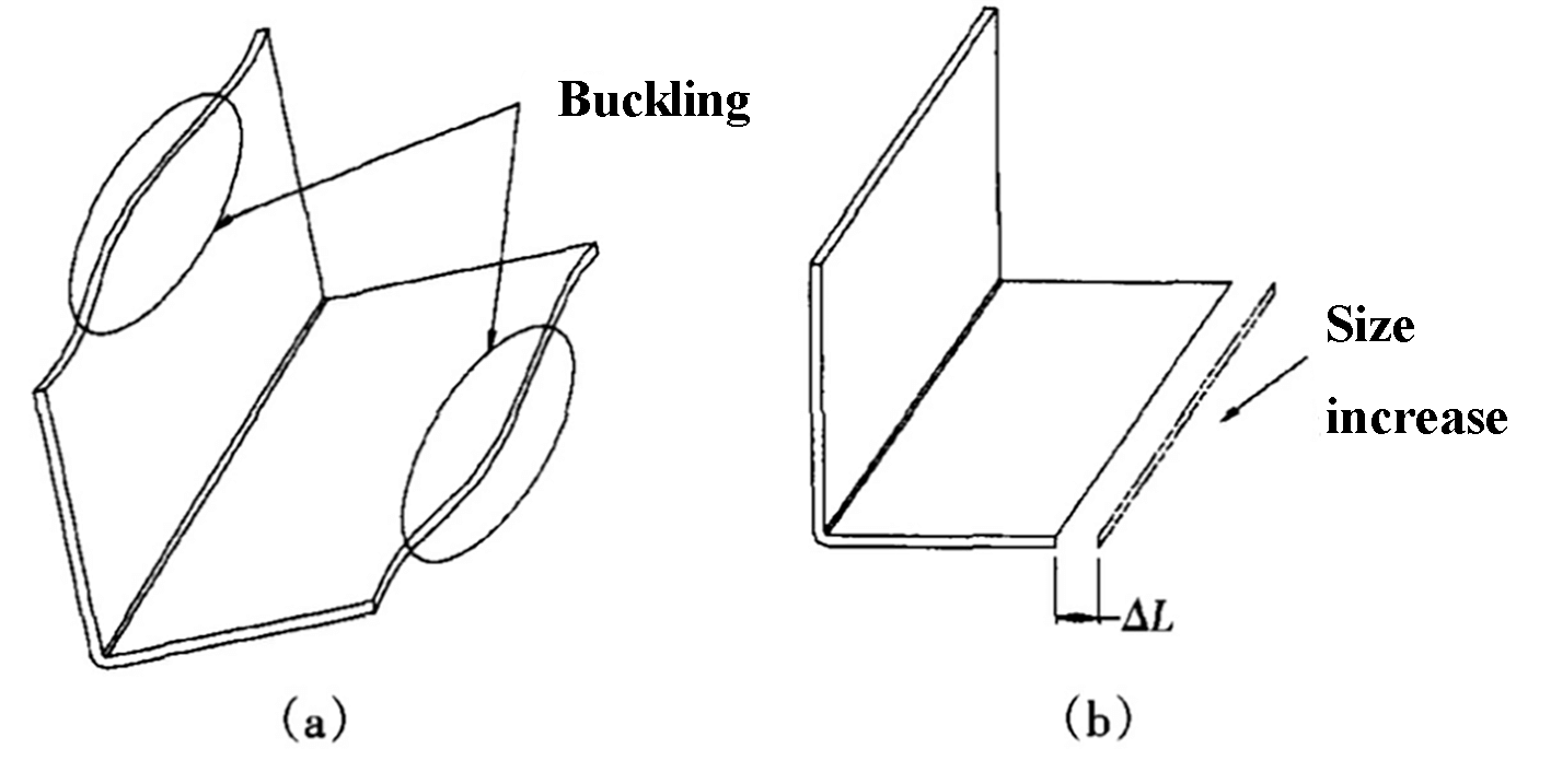
Fig. 1 Forms of flexural failure
a: Buckling deformation b: Size increase
Failure cause analysis
1. Causes of upper die wear
Ultimately, the reason for the phenomenon shown in Figure 1 is due to wear of the upper die of the press brake.
The upper die of a typical press brake is a general die, and a set of general press brake upper dies can be used to bend a variety of sheet metal parts.
In other words, the upper press brake dies are replaced less frequently, and the same group of upper bending dies is used for general bending. In some small factories, a single part may be used and the press brake die never changes.
Any tool or die will wear out over time, but the press brake's top die experiences a high frequency of use.
The R angle of a typical bending top die is small, generally less than 0.5 mm.
As a result, during bending, pressure is concentrated entirely at the R-angle of the upper die, causing a high level of stress at this point, making the upper die susceptible to wear.
2. “Size increase” analysis
As depicted in Fig. 2, wear of the upper die results in an increase in the R angle.
When calculating the unfolding of parts, the size of the bending angle R is one of the factors that affect the unfolding coefficient. Although related information has been introduced, it has not been explained in detail in this context.
For the same part, the greater the R angle, the smaller the unfolding size.
Typically, there are two methods for selecting the flexural expansion coefficient in factories:
- Select the expansion coefficient from an empirical table based on the R angle of the new upper matrix.
- Determination of the expansion coefficient through experimental bending of the new upper matrix to obtain real data.
The first method is more widely used as it is quick and convenient for bending general parts.
The second method is normally used for parts with high bending accuracy and multiple bending angles, as the data obtained is more accurate.
Regardless of the method used to obtain the coefficient of expansion, it is generally solidified once determined.
For example, if the new upper die is used to bend SPCC with material thickness t = 1.0 mm, the expansion coefficient selected in the empirical table is 0.4. This coefficient of expansion will remain at 0.4 for all materials with thickness t = 1.0 mm that are bent using this upper die.
When the wear of the upper die R angle increases, the size of the part that was expanded using the expansion coefficient before wear will inevitably become larger after bending, as shown in Fig.
This difference may not be noticeable for single-angle bending, but if a part is bent multiple times in the same direction, the difference will accumulate. For example, if a part is folded six times in the same direction, the difference in unfolding will be 1.2 mm, adding up to a difference in dimension of 2 mm after bending.
To reduce costs, many factories use medium-carbon steel to manufacture flexible upper dies, which have low wear resistance. After using multiple dies, the R angle can increase from 0.5mm to almost 1mm.
3. “Buckling” analysis
The standard length of a single upper die for a press brake is 835mm, which is generally used in group depending on the type of press brake.
As illustrated in Fig. 3, a group of upper bending dies typically consists of three dies.
Many sheet metal processing plants produce different parts of varying sizes and the bend width can vary greatly.
Typically, sheet metal parts with narrow bend width constitute the majority. As a result, the middle section of the die is often used for bending, as shown in Fig. 3, leading to significant wear on the middle section.
When this group of dies is used to bend sheet metal parts with large width, the pressure at both ends of the internal bending angle is greater than the pressure in the middle wear section, causing the internal angle R of the middle section be greater than the angles at both ends.
Increasing the pressure per unit area and reducing the bending angle R are effective ways to reduce springback.
However, the middle section has two factors favorable to springback. Since the springback in the middle section is greater than that at both ends, a “buckling” phenomenon, as shown in Fig. 1, may occur in the middle section.
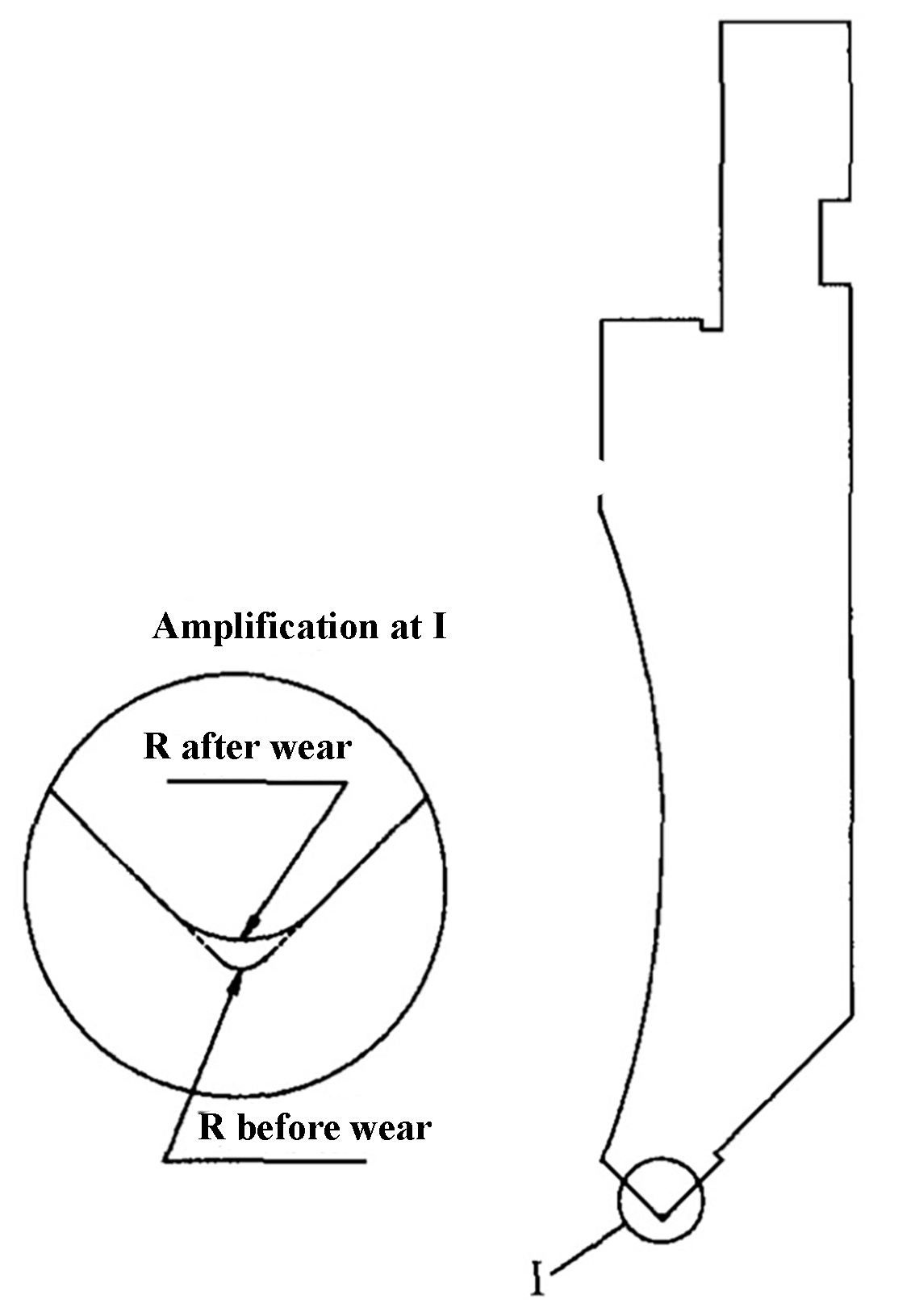
Fig. 2 Upper die wear diagram
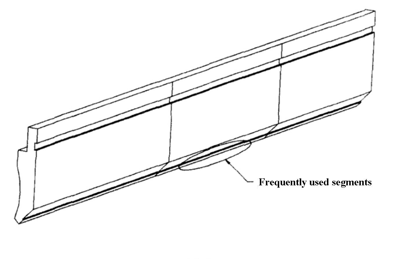
Fig. 3 Bending the upper die
Control method
Die wear cannot be completely eliminated, but by analyzing its causes and implementing appropriate measures, the two failure phenomena shown in Fig. 1a and Fig. 1b can be effectively controlled.
Based on production experience, the following five methods have been summarized:
- Selection of materials with good wear resistance, such as Cr12MoV and SKD-11, to obtain high hardness through heat treatment.
- Improve wear resistance by carburizing or nitriding (for materials with low wear resistance).
- Regularly repair and grind the R angle part of the die, with the frequency determined based on the wear condition of the die, such as half a year or once a year.
- Balance the use of the combined upper die by swapping and rotating them to ensure that the same group of upper dies have balanced R-angle wear.
- Regularly review the development coefficient, with the frequency determined based on matrix wear, such as every six months or once a year.
These methods can be selected based on the actual situation in the factory, and the effectiveness of each method may vary. The best method is the one that maximizes the benefits for the factory.
Conclusion
The sheet metal failure phenomenon discussed in this article is a common occurrence in the sheet metal manufacturing industry. It is hoped that, through this article, more companies that manufacture parts from sheet metal will take the necessary measures to prevent and avoid unnecessary losses.