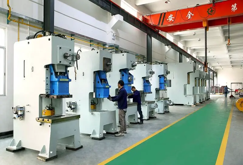
The traditional method of producing silicon steel sheets, used in engines and household appliances, involves installing molds in mechanical presses.
The silicon steel sheet cold stamping die is mainly composed of male and female dies, which are installed in the press to punch the silicon steel sheet into the stator and rotor of the motor or iron chip of the transformer.
During the operation of a silicon steel sheet die, the edge is subjected to impact, shear and bending forces. Furthermore, the edge is also compressed and rubbed by the silicon steel sheet. A special coating on the surface of the silicon steel sheet increases friction and edge wear, which is the main reason for normal die failure.
As a result, die wear is severe and it often needs to be sharpened before it reaches its optimum service life. The number of parts punched in a set of dies is usually less than its theoretical value.
For example, consider the process of molding a silicon steel sheet for a particular engine. Seven types of arrays are required to complete, with a total cost of 190,000 yuan. The hardness of a stamping die for a rotor sheet is 60 to 62Hrc, and it is installed on a 60t stamping machine tool. Normally, the die can punch more than 200,000 parts.
However, the edge of the die hole collapses after being used less than 9,000 times. Grinding the die (usually after 50,000 to 60,000 times) and reapplying it to the machine does not solve the problem. Instead, the collapse persists and cracks appear on the outer edge of the matrix.
During continuous stamping, cracks expand rapidly and the die fails, becoming unusable after less than 20,000 uses. Each time two engines are produced, three types of molds require sharpening, costing between 400 and 800 yuan each time, making the manufacturing cost of the product relatively high.
Especially during trial production of new products, mold manufacturing costs are considerably high and the production cycle is long, doubling the cost of new product development.
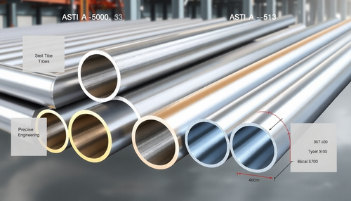
Silicon Steel Sheet Production and Requirements
Silicon steel sheet is a crucial component of motors and electrical appliances. Its performance directly affects electrical energy loss and the efficiency, size and weight of products such as transformers.
Therefore, silicon steel sheet generally must meet the following requirements:
- It must have a smooth surface coating, excellent shape, high dimensional accuracy and minimum thickness variation within the same plate.
- It must have favorable electromagnetic properties and an oriented grain structure that meets application requirements.
The silicon steel sheet cutting process must not only have the typical metal shear characteristics, but also satisfy the following special requirements.
Burr height
The height of the burr on the silicon steel sheet used for stamping should not exceed 0.05 mm. The impact of burrs on the performance of all mechanical parts of the machine is receiving more attention.
The electromagnetic characteristics of generators, motors and transformers using silicon steel sheets are significantly affected by burrs.
Die blanking is used to form the silicon steel sheets used in generators, motors and transformers. Often the gap in die manufacturing is too large or widens due to wear.
During the blanking process, the silicon steel sheet is extruded, causing slight plastic deformation. This deformation remains at the edge of the sheet, resulting in the formation of burrs.
The rotor, stator and transformer core of generators use a large number of silicon steel sheets with burrs.
Burrs on the silicon steel sheet reduce the stacking factor. To install the same number of sheets, the engine volume must increase.
Furthermore, the burr affects the power output of the engine. It has been demonstrated that generator output power can be increased by 0.1% to 0.2% using deburred silicon steel sheets compared to generators that do not use deburred silicon steel sheets.
Impact on generator life
The presence of burrs on silicon steel sheets creates significant gaps between the laminations, which can lead to the production of eddy currents, increased magnetic loss, higher temperatures, noise and even short circuits, resulting in motor failure.
Motors with deburred silicon steel sheets have an average service life of more than 5% compared to motors without deburring.
The processed silicon steel sheets can be stacked manually or automatically, and the joint gap should be minimized. This requires the equipment to maintain high accuracy, including spare parts accuracy, while reaching maximum production capacity. This ensures that the products are practically burr-free after cutting (the height of the burr after longitudinal cutting of the silicon steel sheet should not exceed 0.05 mm).
Otherwise, during rolling, burrs can cause short circuits between laminations, increase eddy current loss, and reduce the filling coefficient of the lamination.
China's relevant standards clearly state that the burr height of silicon steel sheets should not exceed 0.05mm. However, many automobile factories have not implemented effective deburring measures. They still install and use sheets with burrs as small as 0.07~0.1mm, which seriously affects the quality.
In addition, the insulating paint film on the surface of the silicon steel sheet must not be visibly scratched during deburring.
Effect of stress
After cutting, stamping and stacking, silicon steel sheets undergo internal stresses that deform the grains, reduce permeability and increase specific iron loss.
To avoid or minimize these effects, cold-rolled oriented silicon steel sheets are typically treated with nitrogen-filled annealing at a temperature of approximately 800°C after shear processing. This treatment eliminates the stress generated during processing and ensures that the original properties are maintained.
Although tests have shown that the specific iron loss of cold-rolled oriented silicon steel sheet after annealing is reduced by about 30%, many manufacturers choose not to adopt this process due to the associated cost increase.
Steel Sheet Sickle Bending
Given the specialized performance requirements of silicon steel sheets, it is crucial to maintain high standards for their production.
These standards must exceed even the American Society for Testing and Materials (ASTM) lateral bending criteria for general sheared metal, which sets a limit of no more than 6mm/3M in length. As a result, the shear process layout for silicon steel sheets needs to meet even more stringent requirements.
lotus leaf border
The silicon steel sheet that has been cut must be free of any visible waves, commonly called lotus leaf edge.
In the case of waves, the ratio of wave height to wavelength should not exceed 2.5%.
If this condition is not met, the silicon steel sheet will undergo severe plastic deformation, which will result in damage to the domain structure and a significant increase in losses.
Isolation
Insulation damage is not permitted within the shear strip or on the strip surface. Furthermore, the edge of the sheet must be free from any extrusion damage, as failure to meet these criteria may adversely affect the quality of the iron core.
Application of water cutting technology
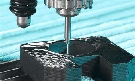
Ultra-high-pressure water cutting, also known as water knife or water jet, is a process that generates a high-energy water flow by pressurizing ordinary water in several stages. This water flow is then directed through a fine nozzle to cut materials at a speed of nearly a kilometer per second.
This cutting technique is known as ultra-high pressure water cutting. Its origins date back to Scotland, where it was discovered. Over a period of 100 years, experimental research led to the development of an industrial high-pressure water shutoff system.
High pressure water cutting is not patented. However, in 1968, a professor at Columbia University, in the United States, introduced abrasives into high-pressure water, which accelerated the cutting process by grinding the materials with the abrasive and the high-pressure water jet.
Today, the United States, Germany, Russia and Italy have achieved breakthroughs in ultra-high pressure water cutting technology, with a maximum cutting pressure of 550MPa. This method is widely used to cut materials such as stone, metal, glass, ceramics, cement products, paper, food, plastics, fabrics, polyurethane, wood, leather, rubber, ammunition and more.
There are three main uses of water cutting:
Firstly, cutting non-combustible materials such as marble, ceramic tiles, glass, cement products and other materials that cannot be processed by thermal cutting.
Secondly, cutting combustible materials such as steel sheets, plastic, fabric, polyurethane, wood, leather, rubber, etc. In the past, thermal cutting could also process these materials, but it often resulted in burning areas and burrs. Water cutting, on the other hand, does not produce such problems and the physical and mechanical properties of the cut materials remain unchanged, which is a significant advantage of water cutting.
Thirdly, cutting flammable and explosive materials such as ammunition and cutting in flammable and explosive environments cannot be replaced by other processing methods.
In terms of water quality, ultra-high pressure water cutting is available in two forms: pure water cutting and abrasive cutting.
Water cut test
The water cutting test for silicon steel sheets is carried out using the Altorf water knife as the main equipment.
The equipment's high-voltage generator (APW38037Z-09A) is equipped with a complete set of superchargers originally imported from AccuStream Inc.
The control system uses PLC instead of relay to achieve flexible computer communication and control.
The cutting platform (APW-2030BA) has a gantry-type structure, which makes it more stable and precise compared to a cantilever structure.
The equipment is equipped with an industrial PC platform with special Windows-based water cutting software and supported by a genuine Windows XP system.
The linear part of the cutting process has a speed of 800mm/min, while the circular arc part has a speed of 300mm/min. The thickness of the silicon steel sheet used in the test is 0.5 mm.
After testing, the product is removed from the water tank on the cutting platform, dried and its size checked. The product presented an out-of-tolerance problem only at the knife entry during round hole cutting. This problem was mainly caused by the knife entering too quickly during programming, causing the hole to appear elliptical. During the retest, this phenomenon disappeared and the burr became smaller than 0.05 mm. The product can be stacked without crushing, and the rest of the product meets the drawing requirements.
Conclusion
Test results from the water cutting process for silicon steel sheets indicate that optimal product quality can be achieved by using appropriate cutting process parameters, closely monitoring water quality and sand particle size, and controlling the entry speed and arc direction.
Water cutting offers several advantages, such as high speed, excellent quality, cost savings and easy product modification. Furthermore, it is especially useful during trial production of new products since there is no need for molds. This significantly reduces the production preparation cycle and minimizes the initial investment required for new products. The results of such tests were highly satisfactory.