Splitting a bamboo stick in half causes both halves to bend – the larger half less and the smaller half significantly more. This phenomenon occurs because the material inherently has tension, and its division disturbs the original balance of this tension, leading to deformation as a way of reestablishing the balance.
Similarly, part deformation by wire EDM (electrical discharge machining) follows this principle, where the cutting process disturbs the original stress balance within the part.
Causes of part deformation in wire EDM
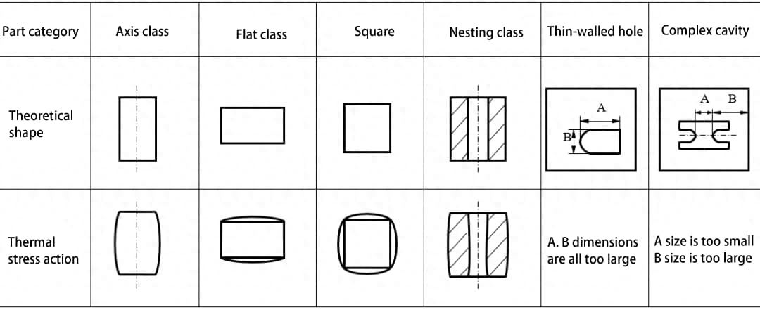
The extent of deformation in wire EDM is related to the structure of the part. Narrow and long cavities and protrusions are prone to deformation, with the degree of deformation depending on the complexity of the shape, aspect ratio and other factors; workpieces with thinner walls are more likely to deform.
If the deformation is minimal and within the precision requirements of the machining process, it may be almost negligible.
However, if the deformation exceeds the required machining precision, it will cause noticeable deviations in dimensions, affecting the shape of the machined part.
Deformation can result from several factors, including material properties, heat treatment, structural design, process planning, and the choice of part fixture and cutting path during wire EDM.
Preventive measures for part deformation
Certain measures can control and prevent deformation in wire EDM.
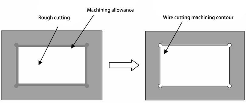
1) Rough machining or cutting with stress relief before final cutting.
Cutting large areas in a material can upset the internal stress balance, causing significant deformation. By removing most of the excess material through rough machining or running stress-relieved cutting paths, most of the internal stress can be eliminated.
For molds with large cavities in EDM, performing two main cuts can be beneficial. Increase the offset by 0.1~0.2 mm for the first main cut to allow for stress relief, and then proceed with the standard offset for the second main cut as shown in the illustrations.
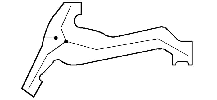
For long, narrow shapes, performing stress-relieved cuts within the shape before machining the outer profile can significantly reduce deformation.
2) Drilling holes for wire threading
When cutting protrusions, starting cutting directly from the outside of the material as shown in figure (a) may lead to deformation due to unbalanced material stress, resulting in opening or closing deformations.
Drilling wire threading holes for closed contour machining, as shown in figure (b), can significantly reduce the deformation caused by wire EDM.
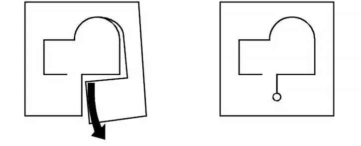
Reducing deformation by drilling holes for threading
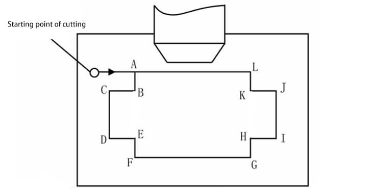
3) Optimizing the cutting path
Generally, it is best to start cutting near the clamping end and arrange the segment separating the workpiece from its clamping part at the end of the machining path, placing break points near the clamping end of the workpiece.
Irrational machining path arrangements can also lead to deformation in wire EDM.
A more rational machining path is: A→B→C→D……→A. If the path is arranged clockwise: A→L→K→J……→A, cutting the workpiece from the clamping piece at the beginning may directly affect the accuracy of the boss due to unreliable clamping.
4) Various cuts
For workpieces still prone to deformation after taking certain measurements, changing the traditional habit of cutting to the right size at once and using multiple cuts can meet the accuracy requirements.
Multiple cuts in wire EDM, which mainly aim to obtain better surface roughness, also significantly reduce the deformation resulting from internal stresses in the mold parts.
5) Optimizing the machining process for multi-cavity mold plates
During wire EDM, the interaction of the original internal stresses and thermal stresses generated by the cutting process can cause unpredictable and irregular deformations, leading to uneven material removal in subsequent cuts and affecting the quality and precision of machining.
To solve this, for high-precision molds, all cavities can be cut in multiple stages. The first cut removes all residue from the cavities.
After waste removal, the machine's automatic repositioning feature is used to sequentially finish the cavities: main cut for cavity a, remove waste→main cut for cavity b, remove waste→main cut for cavity c, remove waste→…… →main cut for cavity n, remove waste→finish cut for cavity a→finish cut for cavity b→……→finish cut for cavity n, completing the process.
This cutting method allows each cavity sufficient time to release internal stresses, minimizing mutual influence and small deformations caused by different machining orders and ensuring the accuracy of mold dimensions.
However, this method involves multiple threading operations and is labor-intensive, making it more suitable for slow wire EDM machines equipped with automatic threading mechanisms. After cutting, measurements confirm that the dimensions meet high precision requirements.
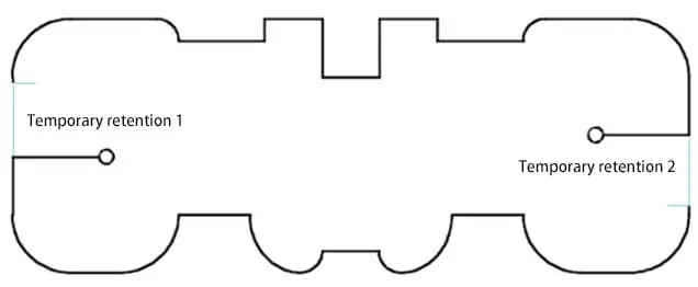
6) Define multiple subsidy segments
For large, complex-shaped parts, it is advisable to define two or more tolerance segments with multiple starting points, as shown in the illustrations.
During programming, the shape is divided into multiple segments and connected sequentially for machining. The contour is machined first, followed by the tolerance segments.