2. Process principle
(1) Since SA335-P91 steel is a fine-grained steel, if the inter-pass temperature is too high during welding, it will increase by 8/5, causing its grains to grow and lose the original strength and toughness of the steel .
However, it is impossible to normalize it during on-site welding.
Therefore, the temperature between passes must be strictly controlled during welding to prevent grain growth.
(2) Heating width, constant temperature, constant temperature time, insulation width and heat treatment insulation thickness are the main factors that affect the toughness of the weld.
Properly increasing the heating width, insulation width, insulation thickness and constant temperature time will help increase the tempering degree of the martensite structure and improve the toughness of the weld.
3. Welding process
(1) The supporting welding adopts double-layer argon arc welding, and the other layers are multi-layer and multi-pass welding processes.
The φ3.2mm electrode is selected and the thickness of a single layer is ≤3mm.
During the welding process, the relationship between welding current and welding speed must be well understood.
Related Reading: Wire Feed Speed and Welding Current
When increasing the welding speed by reducing the thickness of the weld bead, the fast and wide-swing thin layer welding method should be used.
(2) During welding, technicians use a far-infrared temperature measuring gun to measure the inter-pass temperature of each weld layer (the inter-pass temperature is the temperature of 10 ~ 20 mm in front of the weld pool, expressed by the highest value), and the temperature between passes is strictly controlled below 300 ℃.
When the far-infrared temperature measuring gun shows that the temperature exceeds 300℃, stop welding immediately and continue welding when the temperature drops to 230℃.
After welding of each layer is completed, the technician uses a caliper to measure the thickening of the weld bead.
The maximum thickening is ≤ 3mm.
It is strictly prohibited to form a fillet weld between the groove and the weld bead.

4. Welding Precautions
The welding current is selected according to the characteristics of the electrode.
For the electrode with transition coating, the electrode can be melted using a lower current, which can reduce the heat input.
The disadvantage is that the melting point of tungsten in the coating is high, which can easily cause tungsten to be included in the weld.
In short, no matter what type of welding rod is used, it is necessary to ensure the fluidity of the cast iron and the transparent molten pool, especially good fusion at the root of the groove.
On this basis, small specifications will be used as far as possible.
5. Heat treatment process
The post-welding heat treatment adopts the DKPC-12360–12 heat treatment machine, which is heated by the Caterpillar ceramic resistor, and the thermocouple is turned on and fixed.
K-type shielded thermocouple, matching compensation wire and automatic temperature recorder are used, and aluminum silicate insulation cotton is used.
(1) Preheating before welding and temperature control between passes
Electric heating is adopted for preheating.
Four thermocouples are used to control the temperature.
The temperature control points are 3, 6, 9 and 12.
The end of the thermocouple is 20mm from the edge of the welding groove (see Figure 1), and the preheating temperature is 150℃.
When the temperature reaches the constant temperature of 0.5h, backing welding can be started to maintain temperature balance and improve the weldability of the base metal.
During shielded metal arc welding, the temperature rises to 230℃, the overtemperature alarm is set to 260℃, and the inter-pass temperature should be 200~300℃.
The heat treater monitors the temperature and heats immediately if the temperature is too low.
If the temperature is too high, welding should be stopped immediately and restarted when the temperature is restored to 230℃.
The temperature between passes must be tracked and controlled by the heat treatment machine throughout the welding process.

Fig. 1 Thermocouple 20 mm from the groove edge during interlayer temperature control
(2) Post-welding heat treatment
First, the thermocouple must be in good contact with the solder during heat treatment.
The hot end of the thermocouple is generally placed on the first weld near the edge of the groove, and must be firmly clamped with 20# iron wire to prevent the thermocouple from loosening due to thermal expansion at constant temperature, as shown in Fig. Figure 3.
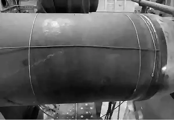
Fig. 2 Place the hot end of the thermocouple on the first weld to ensure good contact between the hot end and the weld

Fig. 3 Thermocouple Installation Diagram for Temperature Control in Zone 4 and Zone 3 of the PWHT
Secondly, during the installation of the heater, the welding bead, welding slag and spatter on the welding surface must be cleaned to close the heater and the welding surface.
After installing the heater, it should be tied with 20# iron wire to prevent expansion of the heating range at high temperatures (see Fig. 4).

Fig. 4 The heater must be tied with thick iron wire after installation
Third, increase the thickness and width of the heat treatment insulation, and the insulation thickness is 100mm, as shown in Fig.

Fig. 5 Thickness and width of heat preservation increasing heating treatment
Fourth, for elbows, tees or welds near valves and cylinder bodies, in addition to track heaters, rope heaters should also be used for auxiliary heating.
Wrap the rope heater in the position where the heater cannot contact the workpiece well, as shown in Fig.

Figure 6
Fifth, the heat treatment parameters of P91 tube are shown in the attached table.
Reasonably increase the constant temperature time, heating width, etc. leads to increased weld toughness.
However, the reduction of weld hardness cannot depend too much on increasing the constant temperature time and heating width, otherwise the base metal will be softened.
Instead, solutions must be found regarding temperature control accuracy and packaging method.
Heat treatment parameters
| Specification mm × mm | Constant temperature time/h | Heating width/mm | Insulation width/mm | Insulation thickness/mm |
| φ fifty-eight thousand and fifty-nine × seventy-three point six | 8 | 600 | 1200 | 100 |
| φ four hundred and thirty-four point seven nine × fifty-seven point six | 8 | 570 | 1200 | 100 |
| φ nine hundred and eighty-five point five eight × thirty-four point six | 5 | 600 | 1200 | 100 |
| φ seven hundred and two point seven × twenty-six point four | 4 | 400 | 1000 | 100 |
| φ five hundred and twenty-three point seven × nineteen point eight | 4 | 400 | 800 | 100 |
Sixth, heat treatment process
After welding, the temperature should be reduced to 110 ℃ for 60 min, so that the martensite can be fully transformed, and then the temperature should be raised for heat treatment.
The post-weld heat treatment is all conducted by “far-infrared” electrical heating, and the heat treatment process is shown in Fig.

Figure 7
6. Precautions for heat treatment
(1) During preheating, the thermocouple should be 20 mm away from the groove edge. When the temperature rises to the preheating temperature, welding must be started at a constant temperature for 30 minutes.
The temperature between passes must be strictly controlled during welding.
Because the temperature measurement of the heat treatment machine is generally delayed by about 30℃, the overheating alarm is set to 260℃.
When the temperature exceeds, stop welding immediately and start welding when the temperature drops to 230℃.
(2) The accuracy of temperature measurement is the most critical factor for the effect of heat treatment.
Thermocouples and temperature recorders must be calibrated by qualified units before use, and the usage time of the thermocouples must be recorded.
Thermocouples must be calibrated once after being used for more than 200 hours.
Since the inter-pass temperature is 200 ~ 300 ℃, the thermocouple checkpoints are 200 ℃, 400 ℃, 600 ℃ and 800 ℃.
(3) The polarity of the compensation wire must be correct when connecting with the thermocouple.
The two connectors of the compensation wire and the thermocouple, as well as the two connectors of the heat treatment machine, must be at the same ambient temperature respectively, otherwise it is easy to cause inaccurate temperature measurement.
The connection between the compensation wire and the thermocouple wire must be reliable using the wiring base.
It is not allowed to directly screw the two wires together. In this way, the line resistance will consume the potential difference and easily cause overheating.