H old F taking time
Hole flanging is a punching method that uses a die to transform the hole edge of the part into a vertical or straight edge at a certain angle.
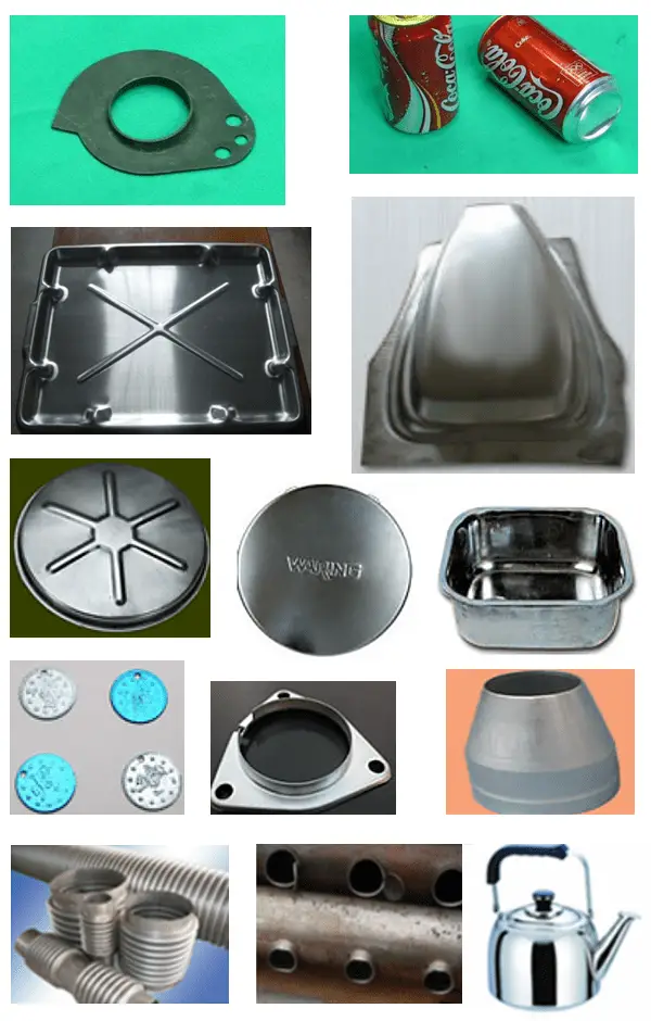
Bore Flange Type:
Depending on the shape of the blank and the edge of the hole being flanged, there are flanged holes on the flat plate and also on the curved surface, such as the flanged hole on the pipe blank; flanged holes can be rounded or not.
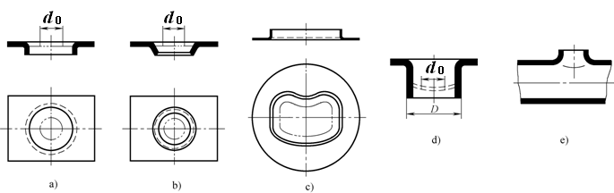
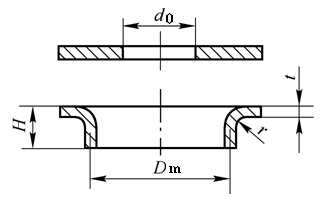
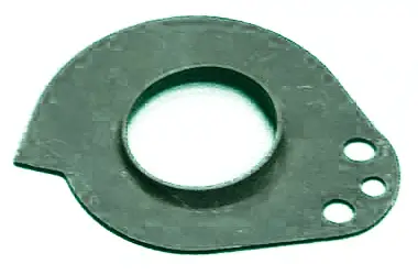
1.1 Round hole flange
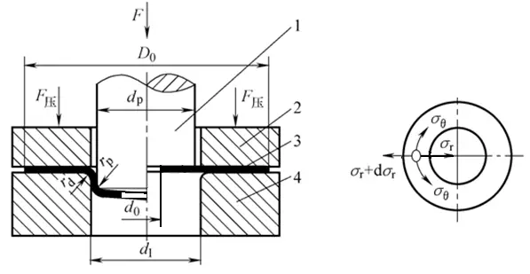
- Deformation characteristics of round hole flange
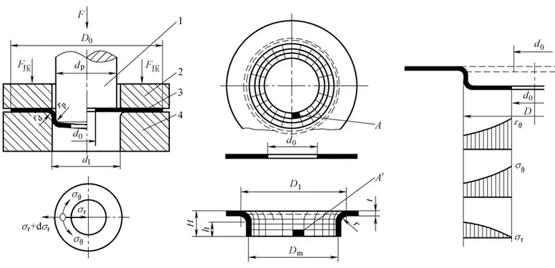
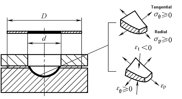
Deformation characteristics of round hole flange:
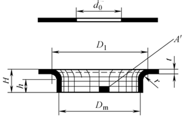
- The deformation is local and occurs mainly in the annular part (d1-d0) at the bottom of the punch. This area is the deformation area of the round hole flange.
- The material in the deformation zone is stretched in the tangential and radial directions, resulting in deformation that is elongated in the tangential and radial directions and has reduced thickness.
- The deformation area is not uniform, the radial stretching is not obvious, the tangential deformation is large, and the more the mouth is extended, the thinner the mouth is.
- Round Hole Flange Forming Limit
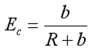
The forming limit is expressed by the hole flanging factor K:
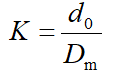
Hole flanging limit factor K min.
Factors affecting the boundary hole flanging coefficient:
- Material properties
- Pre-drilling quality
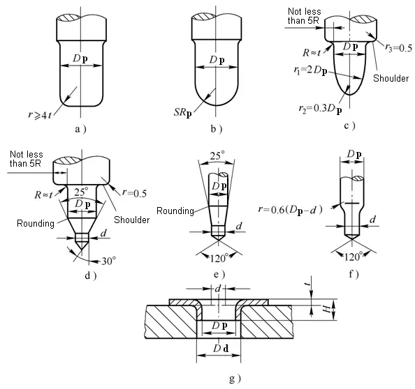
- Puncture shape
- Relative material thickness
- Round hole flanging process design

(1) Round hole technology
- The fillet radius between the vertical edge after flanging and the flange must meet: material thickness t < 2mm, r = (2 ~ 4) t; material thickness t> 2 mm, r = (1 ~ 2) t;
- If the above requirements cannot be met, a reshaping process will need to be added after hole turning to define the required fillet radius.
- After flanging, the thickness of the vertical edge mouth is severely reduced, and the thickness at the thinnest part is:
(2) Process arrangement for round hole
Normally, before flanging the hole, it is necessary to pre-drill the hole for hole flanging, and then determine whether it can be rotated at one time according to the hole height and hole flanging coefficient, and then determine the forming method of hole flange parts.
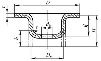
(3) Calculation of plate hole flanging process
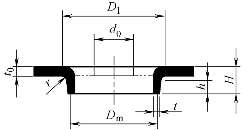
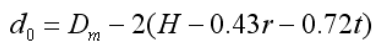
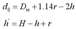
1) Determine the diameter of the pre-drilled hole
2) Calculate the height of the hole to determine whether the hole can be rotated once successfully.
3) Determine the number of rotating holes
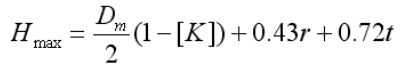
When the hole flange height H
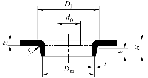
(4) Process the calculation of drawing the bottom hole first and then flanging the hole
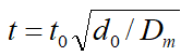
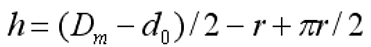
1) Calculate the hole flanging height h that can be achieved after pre-drawing:
2) Calculate the pre-drilling diameter and drawing height before hole flanging:
3) Calculation of deep drawing process
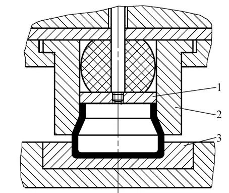
(5) Calculation of hole flanging force
When using a flat-bottom cylindrical punch to flange a hole, it can be calculated as follows:
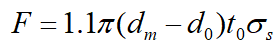
The force for flanged holes with conical or spherical punch is slightly less than the value calculated by the above formula.
- Round Hole Mold
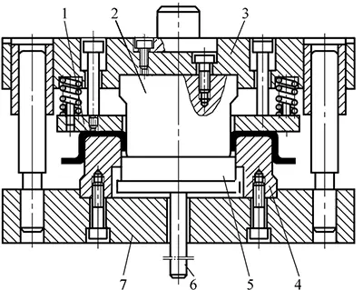
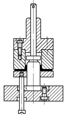
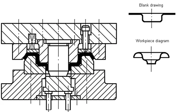
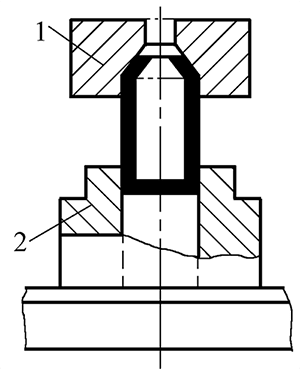
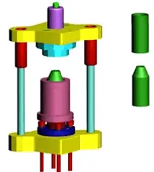
(1) Round hole flange mold structure
Hole Flanging Formal Die
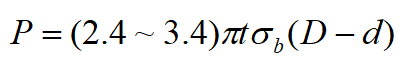
Inverted Hole Flange Mold
Composite dies for molding, deep drawing, punching and hole flanging
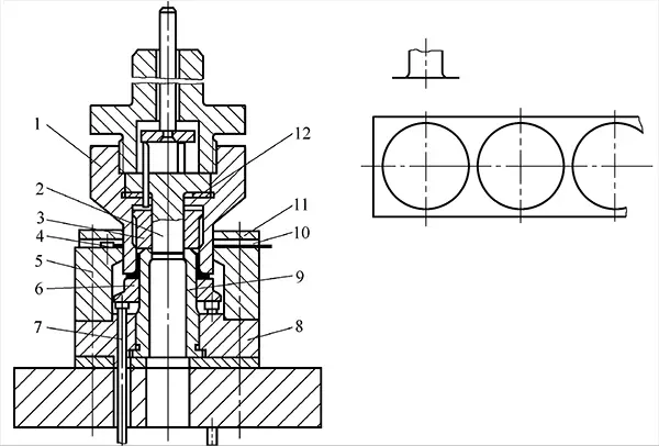
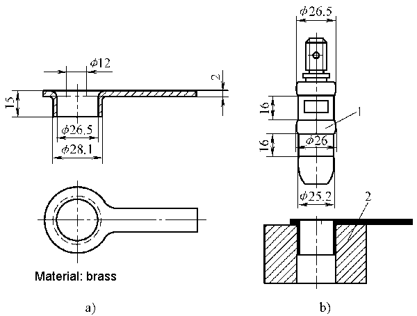
(2) Structure design and size of the functional part of the hole flanging die
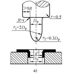
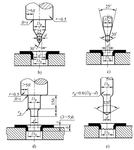
1) Structure and size of round punch
2) C gap between convex and concave matrix
1.2 Non-round hole flanging

Flanging
Flanging refers to a stamping method that uses a die to transform the edges of the product into a vertical or straight edge at a certain angle.
According to the shape of the flanged outer edge:
- Inner curved flange on outer edge
- Externally curved flange on the outer edge
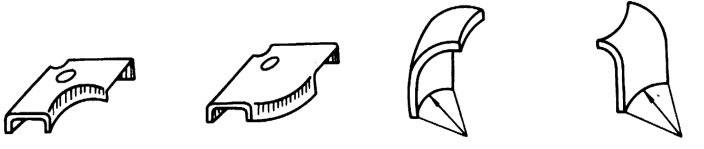
2.1 Inner curved flange on outer edge
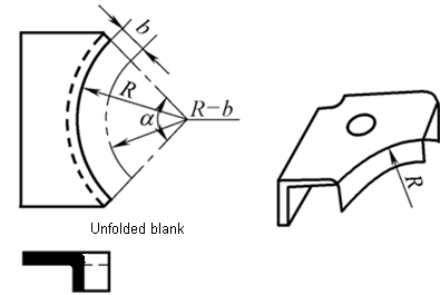
The deformation is similar to a round hole flange, which belongs to stretching.
The deformation area is mainly tangentially stretched, and the deformation at the edges is the largest, which is easy to crack.
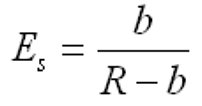
The degree of deformation is:
2.2 Outer curved flange on the outer edge
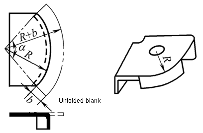
The outer edge curved flange deformation is similar to the shallow drawing and belongs to the compression type deformation.
The deformation zone of the billet mainly generates compressive deformation under the action of tangential compressive stress, which is easy to lose stability and wrinkle.
The degree of deformation can be expressed as:
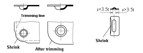
2.3 Outer edge flanging method
- Blank size calculation method
- Mold structure: steel mold or soft mold
- Need to control the rebound
- For vertical edges with different directions, the segmented flanging method must be adopted
Hole Flanging, Flange and Shaping
Further reading: Roughing Flanging
Flanging or rough hole flanging refers to a deformation process that uses a smaller die gap to force the vertical edge thickness to become thinner and increase in height.
Stroking
Necking is a stamping method that uses a mold to reduce the radial dimension of the end of a hollow or tubular part.
3.1 Narrowing deformation characteristics
- Narrowing deformation characteristics
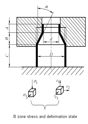
- Zone A – the undeformed zone that has undergone plastic deformation
- Area C-undeformed area awaiting deformation
- Zone B – the deformation zone being deformed
- Preventing instability and wrinkling is the main problem to be solved in the throttling process
- Neck formation limit
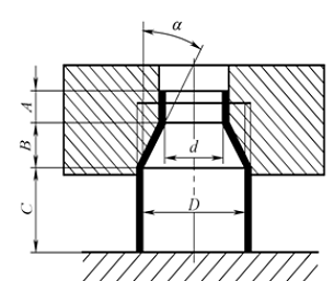
The degree of throttling deformation is expressed by the ratio of the diameter of the neck after throttling to the diameter of the blank before throttling.
Shrinkage coefficient: m = d / D
The minimum value of the throttling coefficient obtained under the premise of ensuring the stability of the throttling member is called the limiting throttling coefficient (m).
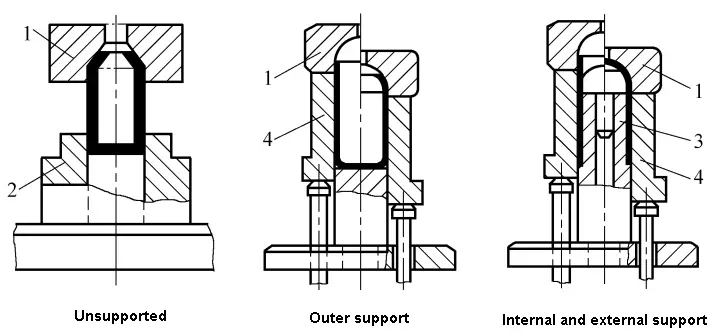
(m) is related to the plasticity of the material and the mold support structure.
Choke mold for different support methods
3.2 Narrowing process design
- Determination of blank size
Refer to Table 6-4 for determination of neck blank size.
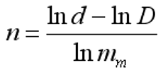
- Confirmation of petting times
When the actual necking coefficient m is less than the limit necking coefficient (m), necking cannot be performed at once.
The number of bottlenecks can be calculated by:
- Calculation of throttling force
When there is no supporting throttling, the throttling force is:
3.3 Neck matrix structure
Necking dies without support
Externally Supported Choke Mold

Composite Narrowing and Widening Arrays
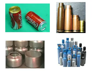
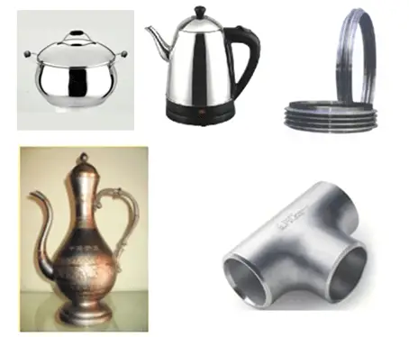
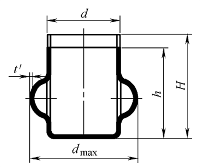
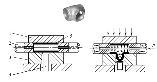
Bulging
Bulging is a stamping method that uses a mold to plastically deform the interior of a hollow part under the action of a bidirectional tensile stress to obtain a convex part.
4.1 Bulging deformation characteristics (two cases)
The deformation area is almost the entire blank or open end, and the open end of the blank is contracted and deformed.
Therefore, the deformation in the deformation area is a deformation state in which the circumference is lengthened, axially compressed, and the thickness is reduced.
The deformation zone is limited to the part to be swollen in the middle of the blank.
The deformation zone mainly produces stretching deformation in the circumferential direction and thinning in the thickness direction.
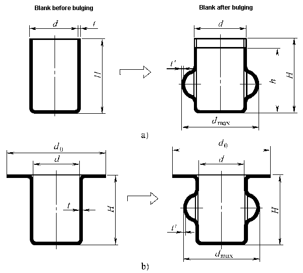
Bulging is a process of stretching formation.
Preventing overflow is the main problem to be solved in the bulging process.
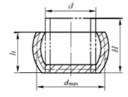
4.2 Bulging formation limit
The degree of bulging deformation is expressed by the ratio between the maximum diameter of the convex bulging obtained after bulging and the diameter of the blank before bulging, that is, the bulging coefficient:
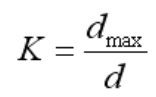
The higher the value of the bulging coefficient, the greater the degree of bulging deformation.
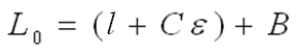
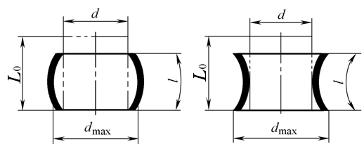
4.3 Bulging process design
- Blank bulge determination
When bulging, the length of the blank when axially allowed to deform freely:
- Calculation of bulging force
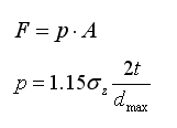
σ Z – The true stress in the protruding deformation area, consider σ Z =σ b in approximate estimation.
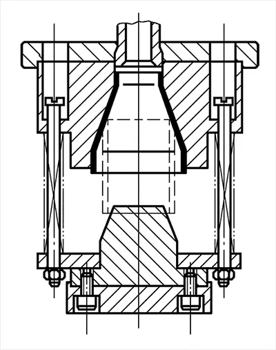
4.4 Bulging method and bulging mold structure
- Steel molds or soft molds can be used. Soft molds are widely used.
- The soft mold medium can be rubber, paraffin, PVC plastic, high pressure liquid and high pressure gas.
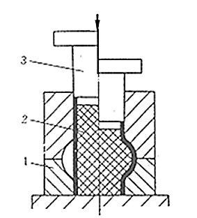
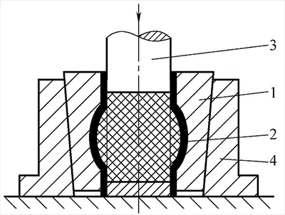
Rubber Lump Mold

High pressure liquid punch bulging
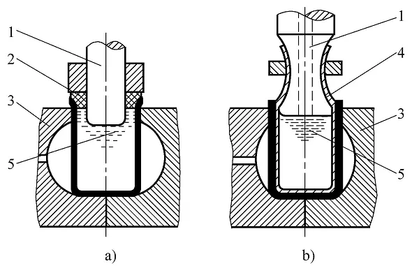
T-joint hydraulic bulging
beading, convex shell pressing and embossing
5.1 Pearling, convex shell pressing
Beading and convex shell pressing are engraving methods that use a mold to produce convex shells or ribs (reinforcement ribs) in the part.
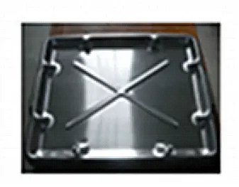
Characteristics of beading formation and convex hulls
- The deformation zone is local
- The deformation zone is stretched in both directions and the thickness is reduced. It is a type of stretching, and the main form of failure is tensile rupture
- The quality of the bulge is good
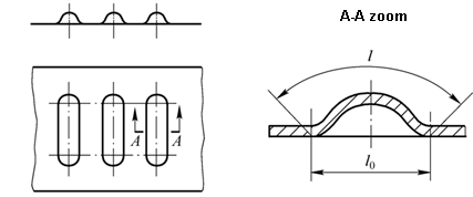
- Beads
The limit of bead formation can be expressed by the amount of change in the length of the deformation zone before and after the bead

- Compress convex hull
The convex hull formation limit can be expressed by the height h of the convex hull
4 types of metal stamping process
- Metal Stamping and Die Design: Suppression
- Metal stamping and die design: bending
- Metal Stamping and Die Design: Deep Stamping
- Metal Stamping and Die Design: Forming