Hydraulic system working principle
The guillotine hydraulic system (see figure below) is mainly composed of motor 3, oil pump 2, pressure cylinder 4, main cylinder 5, auxiliary cylinder 6 and a stack of Bosch-Rexroth valves.
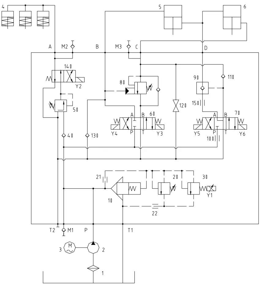
Hydraulic schematic diagram
The whole system is reasonable.
The system pressure is controlled by the electromagnetic proportional overflow valve 30, and the pressing pressure of the pressing cylinder is controlled by the pressure reducing valve 50. Its change can be controlled by changing gears 0, I and II of the pressure adjustment switches. pressure installed in the electrical panel.
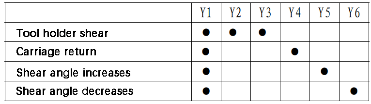
The main action process of the machine is as follows:
Down tool holder:
After starting the oil pump, when the electromagnets Y1, Y2 and Y3 are turned on, the pressurized oil from the oil pump is divided into two forms.
One of the paths enters the pressing oil cylinder 4 through valves 40, 50 and 140, causing the piston rod to move downward against the force of the spring.
The other way enters the upper chamber of the main cylinder 5 through valve 60. The oil in the lower chamber of the main cylinder 5 enters the upper chamber of the auxiliary cylinder 6, and the oil in the lower chamber of the auxiliary cylinder 6 flows back to the fuel tank. oil through valves 80 and 60, which lowers the tool holder.
Return shipping:
When the tool holder reaches bottom dead center, electromagnets Y2 and Y3 are turned off and Y4 is turned on.
Oil from the pressure cylinder flows back to the oil tank through valve 140 under the action of spring force.
The pressurized oil from the oil pump enters the lower chamber of the auxiliary oil cylinder 6 through valve 60 and valve 80. The oil in the upper chamber of the auxiliary oil cylinder 6 enters the lower chamber of the main oil cylinder 5, and the Oil in the upper chamber of the main oil cylinder 5 flows back to the oil tank through valve 60, which drives the tool holder return.
Shear angle reduction:
Changing the shear angle is carried out by changing the amount of oil in the lower chamber of the main cylinder 5 and in the upper chamber of the auxiliary cylinder 6.
While the oil pump is rotating, when the electromagnets Y1 and Y6 are turned on, the pressurized oil from the oil pump enters the series cavity of the main cylinder 5 and the auxiliary cylinder 6 through valves 100, 70, 150 and 90.
Since the oil in the upper cavity of the main cylinder 5 is sealed, the oil under pressure can only push the piston rod of the auxiliary cylinder 6 downwards, thereby reducing the shear angle.
The oil in the lower chamber of the auxiliary cylinder 6 flows back to the oil tank through valves 80 and 60.
Increase in shear angle:
When electromagnets Y1 and Y5 are energized, pressurized oil from the oil pump enters the lower chamber of auxiliary oil cylinder 6 through valves 100, 70 and 110.
Similarly, since the oil in the upper chamber of the main oil cylinder 5 is sealed, the oil under pressure can only push the auxiliary oil cylinder rod 6 upward, thereby increasing the shear angle.
Oil in the series chamber flows back to the tank through valves 90, 150 and 70.
Causes of hydraulic system failures and troubleshooting
Noisy oil pump
Causes:
- Damaged pump parts.
- Foreign body present in the oil suction port.
- The oil pump is empty due to air leakage in the oil suction pipe or low liquid level in the oil tank.
- The oil temperature is too low and the oil viscosity is too high, resulting in excessive resistance to oil absorption.
Solutions:
- Replace the pump.
- Check the oil suction port and remove foreign matter.
- Replace the air leakage part seal or add enough oil into the oil tank.
- Replace with low viscosity oil.
The oil circuit cannot build up pressure and the blade holder does not move
Cause:
Valve core 10 or 60 is stuck or roughened by foreign objects and does not work.
Solution:
Inspect, disassemble and clean.
The shear angle cannot be adjusted
Cause:
The core of valve 10 or valve 70 is stuck or roughened by foreign objects and does not work.
Solution:
Inspect, disassemble and clean.
The tool holder descends and the pressing oil cylinder does not operate
Cause:
The 140 valve core is stuck or roughened by foreign objects and does not work.
Solution:
Inspect, disassemble and clean.