The Coordinate Measuring Machine (CMM) is a precision measuring instrument used in a variety of industries. It is equipped with air brake switches and micro-motion devices on its three axes, allowing precise transmission of each axle. Furthermore, the CMM is equipped with a high-performance data acquisition system to ensure measurement accuracy.
CMM is commonly used for product design, mold equipment, gear and blade measurements, machine manufacturing, tool accessories, steam mold parts, electronic and electrical equipment and other precision measurements.
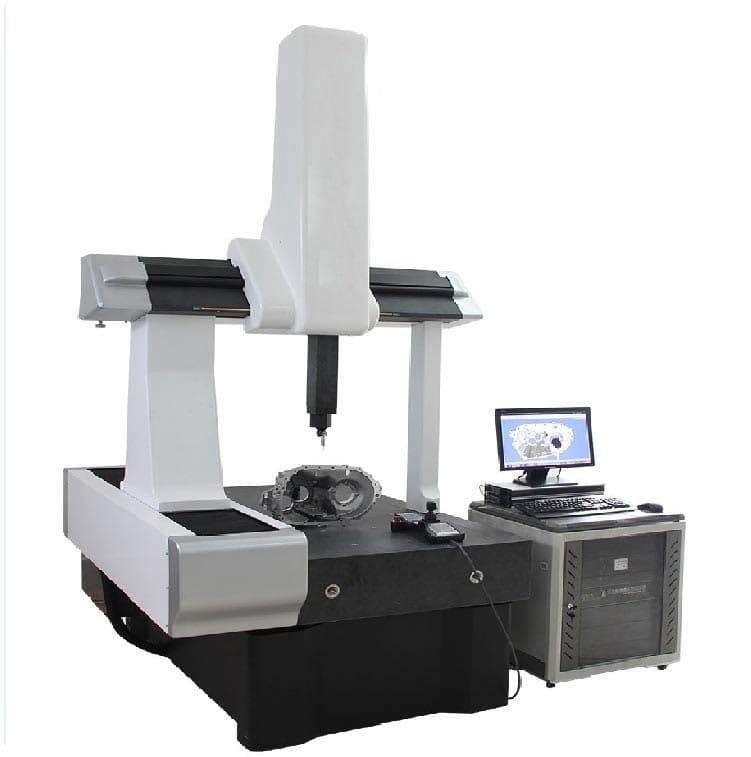
1. Introduction to the instrument
Three-Coordinate Measuring Machine, also known as Three-Coordinate Measuring Instrument, is a device used to measure geometric shape, length and circumferential division within a three-dimensional space. It operates with a detector that can move in three directions along three mutually perpendicular guide rails.
The detector can make contact with the workpiece or measure it without contact. The three-axis displacement measuring system, like a grid ruler, calculates the points (x, y, z) and various functions of the part through a data processor or computer.
CMM measurement capabilities include dimensional accuracy, positioning accuracy, geometric accuracy, and contour accuracy. This instrument is essential to guarantee the precision and accuracy of measurements in various sectors.
Model Introduction
Structure type: three-axis granite, German movable bridge structure surrounded on four sides;
Transmission mode: DC servo system + preload high precision air bearing;
Length measurement system: RENISHAW open grid ruler, with 0.1 μm resolution;
Probe system: Renishaw controller, Renishaw probe, Renishaw probe;
Machine: high precision granite platform (grade 00);
Operating environment: temperature (20 ± 2) ℃, humidity 40% – 70%, temperature gradient 1 ℃/m, temperature change 1 ℃/h;
Air pressure: 0.4 MPa – 0.6 MPa;
Air flow: 25 L/min;
mpee length accuracy: ≤2.1+L/350(μm);
MPEP Probe Ball Accuracy: ≤ 2.1 μm.
Main features
The machine's three axes use high-precision natural granite guide rails. This ensures uniform thermodynamic performance throughout the machine and eliminates precision errors that can result from differences in thermal expansion coefficients between the materials used on the three axes.

Comparison of granite and aviation aluminum alloy
Aluminum alloy material has a large coefficient of thermal expansion.
Typically, the beam and z-axis made of aviation aluminum alloy may be damaged, and its accuracy may change over time with prolonged use.
The platform of the three-coordinate system is made of granite, as is the main axis.
The main axis is constructed of granite, while the beam and z-axis are composed of aluminum alloy and other materials.
The different thermal expansion coefficients of the three axes may cause distortions in measurement accuracy and stability when the temperature changes.
The three-axis guide rail has a rectangular structure entirely made of granite, equipped with high-precision prestressed and self-cleaning pneumatic bearings.
This solid foundation ensures the long-term stability of the machine's precision.
Bearings also provide stable, balanced force along the axial direction, contributing to the longevity of the machine hardware.
A patented air outlet technology with a small hole is used, with an air consumption of 30L/min.
An area of condensation forms in the bearing clearance to neutralize heat generated by friction from bearing movement and improve the overall thermal stability of the equipment.
According to physical theory, when gas passes through a circular hole at a certain pressure, friction generates heat.
In high-precision measurements, even small amounts of heat can affect the stability of the accuracy.
However, when the exit hole opening is smaller than a certain diameter, a condensation effect occurs around the exit hole, which compensates for the weak heat generated by air friction during measurement.
By using this physical principle and small orifice gas outlet technology, the equipment can maintain temperature stability for long periods, thus ensuring accuracy stability.
Comparison of CMM bearings from leading suppliers
The three axes use Renishaw's original gold-plated grid ruler, with 0.1um resolution.
One end of the grid ruler is fixed while the other end is free to expand and contract, reducing its deformation.
The transmission system adopts an internationally advanced design, eliminating any tension deformation of the guide rail to maximize precision and stability.
The steel wire reinforced synchronous belt transmission structure effectively reduces vibration during high-speed movement while providing high strength, speed and durability.
The software used is PTB's comprehensive certified industrial benchmark, Rational-DMIS, which is powerful and easy to use, allowing you to focus on product measurement rather than software learning.
2. Basic components of CMM

X-beam:
Uses precision tilted beam technology.
Guide rail in Y direction:
It employs a unique positioning structure with integrated lower dovetail grooves processed directly into the bench.
Guide rail mode:
It features high-precision pre-loaded, self-cleaning pneumatic bearings comprised of four-way static pressure air-floating guide rails.
Steering system:
It employs high-performance DC servo motors and flexible synchronous toothed belt drive devices.
Each axis is electronically limited and controlled, resulting in faster transmission and better motion performance.
Z axis spindle:
An adjustable pneumatic balancing device increases z-axis positioning accuracy.
Control system:
It uses an imported dual computer specialized three-coordinate control system.
Machine System:
It adopts 3D computer-aided error correction (CAA) technology to ensure long-term stability and high accuracy of the system.
Measurement Software:
Utilizes the powerful 3D-DMIS measurement software package, offering complete measurement functions and online capabilities.
3. Functional principle of CMM
A Coordinate Measuring Machine (CMM) is a type of measuring equipment that consists of a guide mechanism, length measuring element and digital display device in three directions perpendicular to each other, as well as a work table that can accommodate pieces of work (although they may not necessarily be large).
The measuring head can be moved to the measuring point manually or by motorization, and the coordinate value of the measured point is displayed by the reading device and digital display.
This is the simplest and most basic form of measuring machine.
With this machine, the coordinate value of any point within the measuring volume can be displayed by the digital reading and display device.
The sampling point emitter of the measuring machine is the measuring head, which is equipped with grid rulers and reading heads along the X, Y and Z axes.
The measurement process involves contacting the probe with the workpiece and sending a sampling point signal. The control system then collects the coordinate value of the current position of the three-axis machine tool relative to the origin of the machine tool, and the computer system processes the data.
4. CMM Classification

According to the structure of CMM, it can be divided into the following categories:
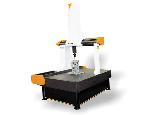
1. Movable bridge type
The most commonly used coordinate measuring machine (CMM) is the movable bridge type.
The axle, the main axis that moves in the vertical direction, is guided by a box-shaped frame to move along the horizontal beam.
The horizontal beam, perpendicular to the axis, is supported at both ends by two columns, forming a “bridge”. The bridge moves along two guide grooves perpendicular to the axis in the horizontal plane.
Due to the support provided by the struts at both ends of the beam, the movable bridge type has lower minimum deflection and greater accuracy compared to the cantilever type.
2. Bridge bed type
In the bridge bed type, the main axis moves in the vertical direction and is guided by a box-shaped structure to move along the vertical axis beam. The beam moves along two horizontal guide rails in the axial direction, which are located on the upper surface of the pillars fixed to the machine body.
This type is similar to the movable bridge type in that both ends of the beam are supported, resulting in minimal beam deflection and greater accuracy compared to the cantilever type.
Furthermore, only the beam moves in the axial direction, which reduces the overall inertia and facilitates manual operation compared to the movable bridge type.
3. Type of gantry
The gantry type of bridge, also known as the floor or door type, differs from the bridge bed type in that it is attached directly to the floor.
This type of structure offers greater rigidity and stability compared to the bed bridge and is commonly used in larger three-coordinate measuring instruments.
Each axis is driven by a motor, providing a wide measuring range. The operator can also work inside the bridge structure.
4. Fixed bridge type
The fixed bridge type features a main axis that moves in the vertical direction and is guided by a box-shaped structure to move along the horizontal beam of the vertical axis.
The bridge, or pillar, is fixed to the machine body, while the measuring table moves along the horizontal plane guide rail, which is perpendicular to the axis, in the axial direction.
Each axis is powered by a motor to maintain position accuracy. However, this model is not designed for manual operation.
5. L-shaped bridge type
The L-shaped bridge is designed to reduce the inertia of the bridge as the axle moves.
Compared to the type of mobile bridge, this design has less inertia in its moving components, facilitating its operation. However, it has a lower level of rigidity.
6. Fixed table cantilever arm type
The movable cantilever type features a main axis that moves in the vertical direction and is guided by a box-shaped structure to move along the vertical axis horizontal cantilever beam in the axial direction. The cantilever beam moves along a guide groove in the horizontal plane, which is perpendicular to the axis.
This type of structure is open on three sides and is convenient for assembling and disassembling parts as it can extend beyond the table. However, the accuracy is lower due to the cantilever design.
7. Single Column Movable Type
The single-column movable type features a main axis that moves in the vertical direction, and the entire column moves along the horizontal plane guide groove, which is perpendicular to the axis, connected to the axis.
The measuring table moves in the axial direction along the horizontal plane guide groove, which is perpendicular to the axis.
This type of structure presents good rigidity in both the measuring table and the pillar, leading to minimal deformations. Furthermore, the linear scale of each axis is positioned close to the measurement axis, ensuring compliance with Abbe's theorem.
8. Single column xy table type
The single pillar measuring table is a movable type, featuring a main axis that moves in a vertical direction.
The pillar is equipped with a shaft guide groove and is fixed to the body of the measuring instrument.
During measurement, the measuring table moves along the axis in the direction of the horizontal plane.
9. Horizontal arm type mobile table
The horizontal arm measuring table is a movable type, with a box frame that supports the horizontal arm to move in the vertical direction (axis) along the vertical pillar. The probe is fixed to the cantilever in the horizontal direction.
The pillar moves in the axial direction along the guide groove in the horizontal plane, which is perpendicular to the axis. The measuring table also moves in the axial direction along the guide groove in the horizontal plane, which is perpendicular to the axis and the axis.
This design is an improvement on the horizontal cantilever type, as it eliminates the deflection caused by the extension or retraction of the horizontal arm in the axial direction.
10. Fixed table horizontal arm type
The horizontal arm measuring platform is a fixed type and has a similar structure to the mobile type.
The measuring table is fixed and the X, Y and Z axes move along the guide groove. During measurement, the pillar moves in the guide groove of the shaft, while the sliding table fixed to the shaft moves in the direction of the vertical axis.
11. Horizontal Arm Movement Type
The horizontal arm movement type features a cantilever axis that moves in the horizontal direction and a box structure that supports the horizontal arm and moves along the spine in the axial direction. The spine is perpendicular to the axis.
The pillar moves in the axial direction along the horizontal plane guide groove, which is perpendicular to the axis, making it unsuitable for high-precision measurements unless the horizontal arm is extended or retracted to compensate for errors caused by weight .
This type of structure is mainly used for vehicle inspection.
12. Type of circular bridge
The closed-loop bridge type is known for its stability as the drive mechanism is located in the center of the bench. This design helps reduce the impact caused by the movement of the bridge, making it the most stable among all three-coordinate measuring instruments.
5. Main advantages
- Surface anodized aviation aluminum alloy;
- High precision self-cleaning pneumatic bearing;
- High-precision European imported grid ruler;
- Patented precision triangular beam technology.
6. Fields of Application
The closed-loop bridge type is widely used in a variety of industries, including automobiles, electronics, machinery, aviation and military, for the measurement of various objects such as boxes, frames, gears, cams, worm wheels, worm ends, blades, curves, curved surfaces, hardware, plastics and more. It is also commonly used in the mold industry.
7. Usage method
Three-coordinate measuring machines (CMMs) are typically classified into three categories: contact measurement, non-contact measurement, and combined contact and non-contact measurement.
Contact measurement is a commonly used method for measuring machined products, pressed products and metal films. Digitizing data points on the surface of the measured object with a CMM is often necessary to analyze processing data or for reverse engineering purposes.
Using the Foundation-Pro CMM as an example, this article will describe the different common scanning methods and operation steps for CMMs.
The scanning operation of a CMM involves collecting data points in a specific area on the surface of the object being measured using the PC DMIS program. This area can be a line, a patch, a section of the part, a curve of the part, or a circle a certain distance from the edge.
The type of scanning depends on the measurement mode, probe type and availability of CAD files. The “scan” option on the control screen is determined by the status button (manual/DCC).
If the DCC method is used for measurement and CAD files are available, the available scanning methods are “open line”, “closed line”, “patch”, “section” and “perimeter” scanning. If only wireframe CAD files are available, the available scanning methods are “open line”, “closed line” and “patch” scanning.
If manual measurement mode is used, only the basic “manual TTP scan” mode is available. If manual measurement is used with a rigid probe, the available options are fixed delta, variable delta, time delta, and body axis sweep.
This article will provide a detailed explanation of the five scanning modes that can be selected when the “utility” menu is accessed and the “scanning” option is selected in DCC status.
1. Open Linear Scan
Open-line scanning is the simplest scanning mode. The probe starts at the start point, scans along a specified direction with a predetermined step size, and ends at the end point.
Open-line scanning can be divided into two cases based on the availability of a CAD model.
(1) Without CAD model:
If the measured part does not have a CAD model, first enter the nominal values of the limit points. Open the “limit point” option in the dialog box, click “1” to enter the starting point data. Then double-click “d” to enter the new X, Y, and Z coordinate values of the direction point (the coordinate point that indicates the scanning direction). Finally, double click on “2” to enter the endpoint data.
Then enter the step size. Enter a new step length value in the “Max Inc” column in the “Direction 1 Tech” column in the scan dialog box. Finally, check whether the defined direction vector is correct, which defines the surface normal vector of the first measurement point after the start of the scan, the cross section and the surface normal vector of the last point before the end of the scan. Click “create” after all data has been entered.
(2) With CAD model:
If the measured part has a CAD model, click on the corresponding surface of the CAD model with the left mouse button at the beginning of scanning, and the PC DMIS program will generate a point on the CAD model and mark it as “1”, the point of departure. Then click the next point to set the scanning direction. Finally, click on the end point (or limit point) and mark it as “2”. Connect the line between “1” and “2”.
For each selected point, the PC DMIS program will enter the coordinate value and corresponding vector into the dialog box. After determining the step size and other options (such as safety plane, single point, etc.), click “measure” and then “create”.
2. Closed Linear Scan
Closed line scanning mode allows scanning of the inner or outer surface of a workpiece. It requires only two values, the “start point” and the “direction point” (PC DMIS considers the start point as the end point).
(1) Data entry operation:
Double click on the boundary point “1” to enter its position in the edit dialog box. Double-click the “d” direction point to enter its coordinate value. Select the scan type (“linear” or “variable”), enter the step size and set the touch type (“vector”, “surface” or “edge”).
Double click on the “start vector” and insert the vector at point “1”. Check the section vector. After entering other options, click “create”.
You can also touch the first measurement point on the surface of the workpiece using the coordinate measuring machine control panel, and then touch the direction point. The PC DMIS program will automatically enter the measured value into the dialog box and calculate the initial vector.
After selecting the scan control mode, measuring point type and other options, click “create”.
(2) Closed-line scanning with CAD model:
If the measured part has a CAD model, confirm “closed line scanning” before measurement. First, click on the surface start point to generate the “1” symbol in the CAD model (when you click, the surface and boundary points are highlighted to help select the correct surface). Then click the scanning direction point.
PC DMIS will provide the coordinates and corresponding vectors of the points selected in the dialog box. After selecting the scan control method, step size and other options, click “create”.
3. Patch Check
Patch scanning mode allows you to scan an area rather than just a single scan line.
This scanning method requires at least four boundary point information, including the starting point, direction point, scanning length and scanning width.
PC DMIS can calculate the triangular patch based on limit points 1, 2 and 3, which are defined by the basic or standard information. The scanning direction is determined by the coordinate value of point D.
If you add a fourth or fifth boundary point, the patch can be square or pentagonal in shape.
When using the patch scanning method, be sure to select “Closed Line Scan” in the check box to scan closed elements such as cylinders, cones, grooves, etc.
The position of the endpoint represents the distance moved up or down while scanning the measured element.
The section plane vector can be defined by the starting point, direction point and starting vector (which is normally parallel to the measured element).
Three methods for defining patch scanning are introduced, using quadrilateral patch creation as an example:
(1) Coordinate value input:
- Double click on the limit point “1” and enter the X, Y and Z coordinate values of the starting point.
- Double-click the boundary direction point “d” and input the coordinate value of the scanning direction point.
- Double-click the “2” boundary point and enter the scan width to set the first direction.
- Double-click the “3” boundary point and enter the scanning width to set the second direction.
- Click “3” and press the “Add” button to display the fourth limit point in the dialog box.
- Double click on the boundary point “4” and enter the coordinate value of the end point.
- After defining the step size and the maximum step size required for scanning, click “Create”.
(2) Touch test mode:
- Select “Patch Scanning” mode and touch the first point at the desired starting point using the probe of the coordinate measuring machine.
- The coordinate value of this point will be displayed in item “#1” of the “Boundary Point” dialog box.
- Tap the second point, which represents the end point of the first scanning direction, and its coordinate value will be displayed in the “d” item of the dialog box.
- Tap the third point, which represents the width of the scanned patch, and its coordinate value will be displayed in the “#3” item of the dialog box.
- Click “3” and select “Add” to add the fourth point to the list.
- Tap the period and the dialog box will close.
- Finally, set the scan line spacing and step length in both directions.
- After selecting the scanning ringtone type and required options, click “Create”.
(3) CAD surface model mode:
- This scanning method is only applicable to parts with a CAD surface model.
- Select “Patch Scanning” mode and left-click on the CAD work surface.
- Highlight “1” in the “Boundary Point” dialog box and left-click the scanning start point on the surface.
- Highlight “d” and click on the surface to set the direction point.
- Click on the surface to set the scan width (#2).
- Click on the surface to set the scan width (#3).
- Click “3”, select “Add”, add additional point “4”, highlight “4”, click to set the scanning end point and close the dialog box.
- After defining the steps in both directions and selecting the desired options, click “Create”.
4. Section Scan
Section Scan mode is only applicable to workpieces with a CAD surface model.
Allows scanning of a specific section of the workpiece.
The scanned section can be along the X, Y, or Z axis direction or at a specific angle to the coordinate axis.
Multi-section scans can be performed by setting the step size.
You can set the section sweep limit point in the dialog box.
By pressing the “Cut CAD” conversion button, you can locate any holes in the CAD surface model and define their boundary line in the same way as Open Line Scanning.
The PC DMIS program will automatically adjust the scan path to avoid holes in the CAD surface model.
To crop the CAD surface model by user-defined surface, follow these steps:
- Enter the “Limit point” option.
- Enter the “CAD element selection” box.
- Select the surface.
- Select the “Cut CAD” option without unchecking the “CAD Element Selection” box.
At this point, the PC DMIS program will cut the selected surface to find any holes.
If there are no holes defined in the CAD surface model, it is not necessary to select the “Cut CAD” option. In this case, PC DMIS will scan according to the defined start and end limit points.
For complex CAD graphics with multiple surfaces, different surfaces can be sectioned into groups. The number of groups is restricted to local CAD surface models.
5. Perimeter Scan
The Perimeter Scan method is only applicable to workpieces with a CAD surface model.
This scanning mode uses the CAD mathematical model to calculate the scanning path, which is offset from the boundary or outer contour by a user-selected distance.
To create a threshold scan, follow these steps:
- First, select the “Limit Check” option.
- If it is an internal boundary scan, select “Internal boundary scan” in the dialog box.
- When selecting a work surface, select the “Select” checkbox, highlight each selected surface, and exit the selection box after selecting all desired surfaces.
- Click on the surface to determine the starting point of the scan.
- Click on the same surface to determine the scanning direction point.
- Click on the surface to determine the end point of the scan. If no end point is provided, the start point will be used as the end point.
- Enter the corresponding values in the “Scan Structure” edit box (including “Added Value”, “CAD Tolerance”, etc.).
- Select the “Calculate Threshold” option to calculate the scan threshold.
- After confirming that the deviation value is correct, press the “Generate Measurement Point” button. The PC DMIS program will automatically calculate the theoretical scan value.
- Click “Create”.
6. Application points
(1) To improve data acquisition accuracy and measurement efficiency, it is important to choose the appropriate sweep measurement mode based on the specific characteristics and modeling requirements of the part being measured.
(2) The workpiece clamping position should be carefully planned to facilitate the measurement process and probe movement. To ensure modeling accuracy, try to arrange the probe so that it completes scanning measurements of all objects at once when clamping the workpiece.
(3) The selection of sweep measurement points should include key points of the part contour geometric information, and measurement points should be added appropriately on parts with significant curvature changes.
8. Data Management
1. Data Conversion
Tasks and Requirements for Data Conversion:
(1) Convert the measurement data format to the IGES format recognized by CAD software and save it with a product name or a user-specified name after combination.
(2) Data with different products, different attributes and different placements that are prone to confusion should be stored in separate files and should be organized and separated into IGES files.
Data conversion is performed by the Coordinate Measurement Data Processing System.
For the operation method, refer to the software user manual.
2. Relocation and integration
App background
During the product surveying and mapping process, it is often not possible to measure the geometric data of the product in the same coordinate system for various reasons.
The first reason is that the size of the product exceeds the stroke of the measuring machine.
The second reason is that the measuring probe cannot reach the opposite side of the product.
The third reason is that data is missing after the part is removed and needs to be measured again.
In these cases, it is necessary to measure each part of the product in different positioning states (i.e. different coordinate systems), which is known as Product Relocation Measurement.
In modeling, data from different coordinate systems in different positioning states must be transformed into the same coordinate system, which is called Relocation Data Integration.
For complex or large models, multiple positioning measurements are often required in the measurement process.
The final measurement data must be relocated and integrated multiple times according to a specific conversion path, to convert the measured data at each placement into measurement data under a common placement benchmark.
Relocation Integration Principle
There is a discrepancy between the measurement data after the part is moved (relocated) and the measurement data before the movement.
To integrate the relocated measurement data into the pre-movement data, a shape must be established that can be measured before and after relocation on the workpiece (referred to as the Relocation Benchmark). As long as the shape measurement results after relocation match the measurement results before relocation through a series of transformations, the relocated measurement data can be integrated with the data before movement.
The Relocation Benchmark serves as a link in the integration of relocated data.
PID control stands for proportional, integral and differential control.
P Parameter:
The system's response process to position error can be determined by analyzing the relationship between the stability, stiffness and positioning error of the system.
A lower value indicates a more stable system with reduced oscillation, but with weaker stiffness and greater positioning error.
On the other hand, a higher value results in better rigidity and less positioning error, but the system may suffer from oscillations.
Parameter I:
The control of static positioning error caused by friction and load is determined by the relationship between the control value and the arrival time at the theoretical position.
A lower value results in a longer arrival time.
A higher value increases the probability of oscillation in the theoretical position.
Parameter D:
The parameter provides stability and damping to the system, preventing excessive error changes.
A lower value results in a faster system response to position error.
A higher value results in slower system response.
9. Daily maintenance
To prevent the “holiday syndrome” it is necessary to change the way CMM is managed.
The CMM is made up of complex components, including mechanical parts, electrical control parts, and computer systems.
It is important to properly maintain the CMM when using it to measure workpieces in order to extend its service life.
The basic maintenance of the CMM is explained below from three perspectives.
Mechanical parts
There are several types of mechanical components in a Coordinate Measuring Machine (CMM). To ensure proper functioning, it is important to perform daily maintenance on the components of the transmission system and the air circuit system.
The frequency of maintenance should be determined based on the CMM operating environment. In fine measuring rooms with ideal conditions, regular maintenance every three months is recommended. However, in environments with high levels of dust or where the temperature and humidity do not meet the requirements for proper functioning, maintenance must be carried out monthly.
For regular maintenance of measuring machines, the factors affecting measuring machines must be understood:
Influence of compressed air on the measuring machine
To choose a suitable air compressor, it is advisable to incorporate an additional air tank. This will increase the longevity and pressure stability of the air compressor.
It is important that the air compressor starting pressure is higher than the required operating pressure.
When turning on the equipment, it is recommended to first activate the air compressor and then turn on the power.
Influence of oil and water on the measuring machine
Compressed air is crucial for the proper functioning of a measuring machine, so it is essential to properly maintain the air circuit.
The following tasks must be performed regularly:
- Before using the measuring machine every day, inspect the pipes and filters and drain all water and oil from the filter and air compressor/air tank.
- Clean the filter elements of the attached filter and pre-filter at least every three months.
- Shorten the interval if air quality is poor. Over time, oil pollution can clog the filter elements, reducing the actual operating air pressure of the measuring machine and compromising its normal operation.
- Regular cleaning of the filter elements is necessary.
- Cleaning the guide rail daily to remove oil stains and dust will help keep the floating guide rail in good working condition.
To protect the guide rail of the measuring machine, good work habits must be formed
To ensure the safety of the guide rail, place a cloth or rubber lining underneath.
After work or completion of parts, be sure to clean the guide rail.
When using the measuring machine, strive to maintain a consistent ambient temperature in the measuring room, such as during calibration.
Keep in mind that electrical equipment, computers and personnel generate heat. During installation, place electrical equipment, computers, etc. at a sufficient distance from the measuring machine.
Strictly manage the measurement room and minimize the presence of extra personnel.
Management of the operating environment for high-precision measuring machines must be especially rigorous.
Influence of air conditioning wind direction on the temperature of the measuring machine
For measurement room air conditioning, it is best to choose variable frequency air conditioning.
Variable frequency air conditioning has excellent energy-saving capabilities and, most importantly, strong temperature control capabilities. At normal capacity, it can regulate the temperature within ±1℃.
Please note that the air from the air conditioner cannot be at 20℃ and must not be directed directly into the measuring machine. To avoid this, the wind direction can be redirected towards a wall or side, causing a large temperature difference in the environment.
The air conditioning must be installed in a planned manner, blowing air into the main area of the room. The wind direction should be upward to create a large cycle (not towards the measuring machine) and balance the internal temperature as much as possible.
If possible, an air duct can be installed to bring air to the top of the room through double-layer orifice plates, with the return air outlet at the bottom of the room. This will create an uneven airflow and make temperature control in the measurement room more efficient.
Influence of air conditioning on time on engine room temperature
You are required to turn on your workplace's air conditioning system every morning and turn it off at the end of the day.
After the temperature in the waiting room has stabilized for approximately four hours, the accuracy of the measuring machine will also become stable.
However, this operating procedure significantly impairs the efficiency of the measuring machine, making it difficult to guarantee accuracy during winter and summer.
This will also have a substantial effect on the normal stability of the measuring machine.
Influence of machine room structure on machine room temperature
To maintain a constant temperature in the measuring machine room, thermal insulation measures must be implemented.
If there are windows, double-glazed windows should be installed and direct sunlight should be avoided.
Using a transition room will help reduce temperature loss.
The air conditioning system in the mechanical room must have a capacity comparable to that of the surrounding room.
If the engine room is too large or too small, there will be difficulties controlling the temperature.
In areas with high humidity in the South or during the summer or rainy season in the North, sudden shutdown of the cooling air conditioner may cause rapid condensation of water vapor in the air on the low-temperature parts and guide rails of the measuring machine, leading to to serious corrosion of the air floats and some parts of the machine, affecting its useful life.
Excessive moisture can also cause corrosion or short circuits on circuit boards in computers and control systems.
Low humidity can severely impact granite's water absorption and cause warping.
Dust and static electricity can damage the control system.
Therefore, the humidity in the machine room should be controlled within 60% ± 5%.
Poor sealing and high air humidity in the measuring machine room are the main causes of high humidity.
In areas with high humidity, the mechanical room should be better sealed and dehumidifiers should be added if necessary.
To resolve this issue, the management mode should be changed from “cleaning before vacation” to “cleaning during work”, and the air conditioning and dehumidifier should be turned on to remove moisture.
Regularly cleaning dust from your computer and control system will reduce or prevent potential problems.
Using standard parts for machine inspection is effective but relatively complicated and can only be performed periodically.
A more convenient method is to use a representative part, compile an automatic measurement program, and perform multiple measurements after checking the machine's accuracy.
The results can be calculated according to statistical laws and a reasonable value and tolerance range can be recorded.
The operator can frequently check this part to determine the accuracy of the machine.
Z axis balance adjustment
The Z axis scale of the measuring machine is divided into weight scale and pneumatic scale, which helps to balance the weight of the Z axis and ensure its stable operation.
If the air pressure balance switch is accidentally activated, the Z axis will be unbalanced.
To resolve this issue, follow these steps:
- Rotate the measuring base 90 degrees to prevent the measuring head from making contact during operation.
- Activate the “emergency stop” switch.
- A person must physically hold the Z axis and move it up and down to assess their balance.
- Another person should adjust the air pressure balance valve, making small adjustments at a time.
Two people can work together to adjust the Z-axis balance until it is balanced when moving up and down.
The limit switch serves to protect the machine and establish its initial position.
Typically, the limit switch is a contact switch or a photoelectric switch.
The contact switch tends to change position when manually pushing the shaft, causing poor contact.
To ensure good contact, the switch position can be adjusted accordingly.
When using a photoelectric switch, it is important to check that the position of the insert is normal and regularly remove any dust to maintain its proper functioning.

10. CMM Use and Safety Precautions
Only individuals who have received training and obtained operational certification are authorized to operate the CMM.
Before starting the machine every day, the control cabinet can only be opened when the air supply pressure meets the requirement: the air supply pressure must be ≥ 0.65 MPa and the machine air pressure must be ≥ 0.4 MPa.
If the height of the oil-water mixture in the triple water storage cup exceeds 5 mm, the water must be drained manually.
If the machine's air supply pressure is normal, but the pressure in the triplet cannot be adjusted to the normal value, the filter element will need to be replaced.
The CMM operating environment must have a temperature of 20 ± 2°C and a relative humidity of 40-75%.
The regulated power supply must have an output voltage of 220 ± 10V.
No objects should be placed on the machine guide rail.
Do not touch the work surface of the guide rail with your hands.
Before starting the machine every day, wipe the surface of the three-axis guide rail with a high-quality pure cotton cloth dipped in anhydrous alcohol, and the machine can only be operated when the surface of the guide rail is dry.
Alcohol should not be used to clean the painted surface or the grating ruler.
The boot sequence is as follows:
- Turn on the power box
- Turn on full air supply
- Turn on the dryer cold
- Turn on the air valve
- Turn on the control cabinet power supply
- Turn on the pedestal controller
- Start the engine when the operation box light is on (emergency stop button must be released)
- After the system self-inspection is completed, start the measurement software, zero the three axes (go home), and enter the normal operating state after automatic completion.
The machine must return to zero after each start.
Before returning to the zero point, move the probe to a safe position to ensure there are no obstacles during probe reset and upward movement in the Z axis.
When replacing the probe, use the special tools provided with the machine and calibrate the new probe:
- Start the software before opening the measurement software (recommended method)
- If the measurement software is turned on, press the emergency stop switch on the operation box and turn it on after replacement.
If a probe error message dialog box appears, close it (or enter 100.0.0.1 in the Web address input column to view the error history and message). This message will be automatically cleared during the next boot.
During manual operation, press the slow key when approaching the sampling point.
When rotating the probe, calibrating the probe, automatically changing the probe, or performing any other operation, make sure there are no obstacles in the probe's movement path.
When the program is not in use or not programmed, set the speed in the operation box to 0.
During the first run of the program, reduce the speed to 10-30% and monitor whether the operating track meets the requirements.
When handling and positioning workpieces, first move the probe to a safe position and make sure that the workpieces do not collide with the worktable, especially the guide rail surface of the machine.
The shutdown sequence is as follows:
- Move the Z axis to the left, forward and upward of the machine and rotate the probe angle to A0B0.
- Clean the work surface.
- Turn off the pedestal controller, control cabinet power supply, air valve, dryer, main air supply, and power box, in this order.
Standard steel balls that are not used for a long period of time should be sealed with oil to prevent rust.
When fixing a part with inlay on the granite surface, the torque must not exceed 20 Nm.
If any abnormal conditions are detected (excluding error messages related to probe replacement), record the error information displayed by the software, contact Hexcon's technical service department by fax or telephone, and do not perform inspection or maintenance without guidance and permission.
Do not install any software that is not related to the three coordinates on the computer to ensure reliable system operation.
The air conditioning must operate 24 hours a day, and maintenance must be carried out in the autumn to ensure the normal operation of the three coordinates.

CMM Machine FAQ
What is CMM?
Three-coordinate measuring machine is commonly referred to as a measuring system that determines the three-dimensional coordinates of the surface points of a workpiece through the relative movement of the probe system and the workpiece.
It is also known as coordinate measuring machine (CMM) or three-coordinate measuring instrument.
Does temperature have a big influence on the CMM measurement results?
CMM is a complex measurement system that combines light, machinery, electricity, computer and control technology, which means there are many factors that can affect the uncertainty of measurement results.
However, for medium and small coordinate systems, the main factor affecting the uncertainty of measurement results is the deviation of the standard measurement temperature (20°C) from the ambient temperature. To obtain accurate coordinate measurement results, the ambient temperature must be strictly controlled within the range specified by the coordinate machine instructions.
Which CMM items need to be calibrated and how long is the recalibration interval?
The current calibration standard for three coordinates is the JJF1064-2000 calibration specification for coordinate measuring machines, which specifies that the calibration items are length measurement indication error and detection error.
It is recommended to calibrate once a year.
When does the CMM need to calibrate 21 errors?
The 21-point error is the basis of CMM accuracy, and its calibration is complex.
Although it is not specified in the standard, 21-point error calibration is required under the following circumstances: when accepting a new machine, when the length measurement error calibration result is outside the tolerance range, after the coordinate machine has been relocated and after the coordinate machine was repaired.