
Layout of the steering system or steering system components
Various components of the steering system are shown in Figure 4.1.
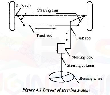 steering system layout
 Following are the main components of the steering system.
1. Steering wheel
2. Steering column or shaft.
3. Steering gear
4. Drop arm or pitman arm
5. Ball joints
6. Drag the link
7. Steering arm
8. Short shaft
9. Left spindle and kingpin
10. Left tie rod arm
11. Rod or tie rod
12. Right tie rod arm, spindle and king pin
13. The steering stops.
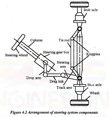 steering system components
 1.Steering wheel:
It is the steering wheel for steering a vehicle by the driver. It contains traffic indicator switch, light switch, wiper switch, etc.
2. Steering linkage:
The steering wheels are turned by the steering knuckle. The steering linkage consists of pitman arm, ball joints, drag link, steering arm, spindle, tie rod and king pin assembly.
Different forms of direction bonds are shown in Figure 4.3.
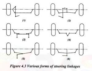 forms of direction bonds
(a) Pitman arm:
It is also called a drop arm, which converts the steering gear output torque into force for the drag link. It is connected to the steering gear sector shaft by a split joint. Full serrations or partial splines are used to transmit torque from the sector shaft to the pitman arm. The split arm is tightened around the sector axis by a set screw. It is done to differentiate between male and female serrations or striations. The end of the pitman arm connected to the drag link has a tapered hole. The ball pin on the drag link is fixed in this hole.
(b) Ball joints:
These joints are connected at both ends of the drag link and tie rod. They perform the angular displacement, the rotational movement of the drag link and steering bar produced by the rotation of the front wheel and suspension articulation.
(c) Drag link:
It is connected between the pitman arm and the steering arm. It is a single prayer forged component having a ball joint socket formed at the end in some other cases.
(d) Steering arm:
It is also a forged component that is connected to the steering knuckle. During turning, the drag bar force is converted into a turning moment about the left king pin. The steering arm is connected to the spindle via a keyway, locking cone and nut. The arm is extended to the front or rear axles according to package constraints. The end of the steering arm connects to the drag link and a tapered hole receives the ball pin.
(e) Left spindle and kingpin:
The torque obtained by the steering arm turns the left spindle, wheel and tire around the king pin.
(f) Left tie rod arm:
The left tie rod arm is connected to the spindle in the same way as the steering arm. It converts the torque available to turn the right wheel into force on the steering rod. The tie rod has a tapered hole to receive the tie rod ball pin.
(g) Tie rod:
The tie rod is a tubular element. The left and right tie rod arms are connected by this tie rod. Force is transmitted between these two components. The tie rod ends have female threads. But the ball joint shafts have corresponding male threads. Threaded connections are held together tightly by locking clamps after setting the correct length. The length of the tie rod is adjustable to the specified value.
In the direct cross type steering linkage, the pitman arm is directly connected to a tie rod which in turn is connected to another tie rod. The other end of the tie rod is connected to the steering arms.
(h) Right steering arm, spindle and kingpin:
It converts the force from the tie rod into a moment to rotate through the knuckle arm, the right spindle wheel and the tire over the kingpin. The right spindle and king pin assembly are merely similar assemblies on the left side. But it has no steering arm connected to it.
(i) Steering stops:
Stops are used to limit the angular deflections of the front wheels. It also prevents tire friction against the frame caused by tire wear. These steering stops are used in two different locations. First, they are fixed in the trajectory of movement of the steering arm or lowering arm. Then they are fixed in the path of movement of the steering knuckle.
3. Steering shaft:
The steering shaft is mounted inside the hollow steering column. When the steering wheel is turned, the steering shaft also turns. Due to this, the movement is transmitted to the steering gear.
4. Steering gear:
The pitman arm is splined to the steering gear rocker arm at one end and the other end is connected to the drag link by a ball joint.


1comment
Qual seria o torque de aperto do pino esférico? Não dá porca e sim do pino do pivô