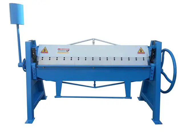
Manual Folding Machine Overview
Usage and performance
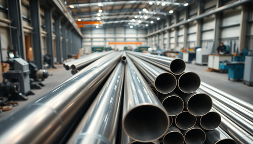
This series of manual bending machines is widely used in various industries to bend and bend steel sheets, non-ferrous metals and stainless steel sheets with a length of up to 2.5 meters and a thickness of up to 2mm. They are particularly popular in the production of household appliances, stainless steel kitchenware, lighting fixtures, furniture hardware, ventilation systems and air conditioning equipment.
The machines have fully manual operation with a positioning device, which makes them ideal for mass production of irregular parts with a fixed angle.
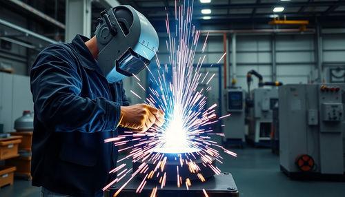
The bending process is carried out using the upper and lower blades, ensuring that there is no relative movement or impact throughout the process. This results in a smooth, shiny surface on the workpiece, making it particularly suitable for manufacturing stainless steel parts.
Locking is achieved through the use of bevel gears, screw rotation or cams, providing smooth, reliable operation. The machines have a simple structure, making maintenance and adjustment easier.
Main specification and technical parameters
| Portable type (bevel gear locking) | ||||||
| Model | Max Plate Thickness | Max bending width | Max bending angle | Weight | Max. Part Dimension | Tools |
| WS1.5×1300 | 1.5 | 1300 | 60° | 320 | 1950×650×1500 | Segmented Blade |
| WS1.5×1500 | 1.5 | 1500 | 60° | 360 | 2150×650×1500 | Segmented Blade |
| WS1.5×2000 | 1.5 | 2000 | 60° | 450 | 2650×650×1500 | Segmented Blade |
| WS1.2×2500 | 1.2 | 2500 | 60° | 550 | 3150×650×1500 | Segmented Blade |
| TDF1.5×1300 | 1.5 | 1300 | 60° | 320 | 1950×650×1500 | Segmented Blade |
| TDF1.5×1500 | 1.5 | 1500 | 60° | 360 | 2150×650×1500 | Segmented Blade |
| TDF1.5×2000 | 1.5 | 2000 | 60° | 450 | 2650×650×1500 | Segmented Blade |
| TDF1.2×2500 | 1.2 | 2500 | 60° | 550 | 3150×650×1500 | Segmented Blade |
Structure and adjustment instructions
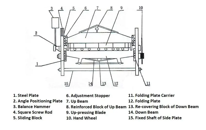
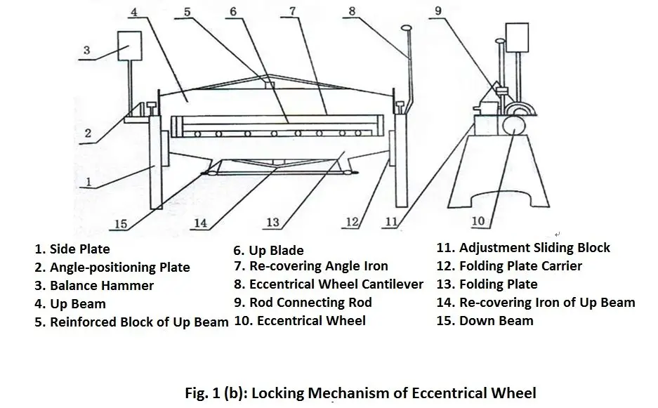
This series of manual bending machine tools, as shown in Figure 1, consists of upper and lower beams, plate bending components and blades. These three components were adjusted to a rotational center, allowing users to adjust related parameters based on machine specifications and sheet thickness.
The adjustable parts of this series of manual press brake are as follows:
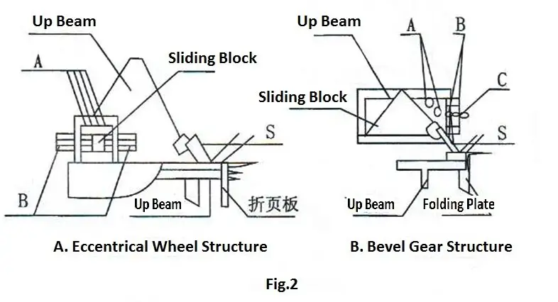
- Loosen screw A connecting the left and right seat of the ram and the upper beam and adjust screws B or C until S=1.3t(t=plate thickness), when the upper and lower blades are parallel to each other, adjust screw A, too small S will be harmful to the blades.
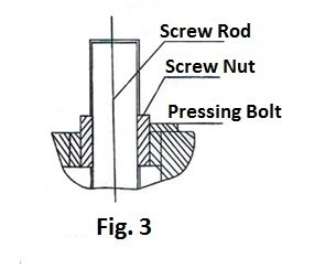
- Adjust the upper beam in the vertical direction (limit to the bevel gear lock folding machine), if any error appears in the vertical position between the tip of the upper bean blade and the surface of the lower blade, loosen the gasket screw and rotate the nut up to the upper vertical and lower beam in parallel and then locking the gland screw again.
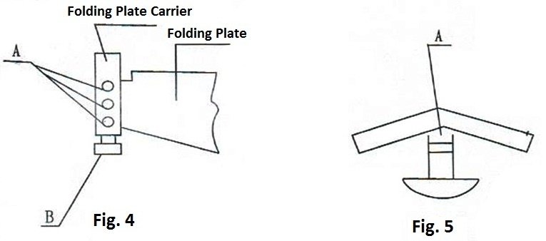
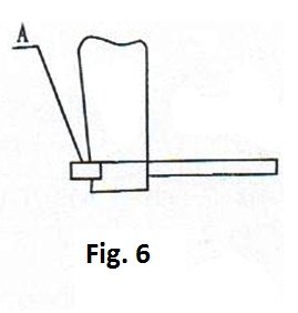
- Adjust the folding plate in the vertical direction (as shown in fig.4)
First, loosen the screw A connecting the folding plate and the folding plate seat, then adjust the bilateral screw B until the folding plate blade and the beam blade are on the same line, and finally lock the screw A again.
- Adjusting the straightness of the prestress and bending plate
All support points on the upper beam, lower beam and bending plate are distributed at both ends, it is inevitable that some deflection will arise in the plate bending process, which directly affects the straightness of the part, in order to overcome the deficiency, The machine is equipped with crowning device, through adjusting nut A to add some prestress in the center of the beam and folding plate (maximum adjustable height 0.5mm) to compensate the deflection deformation to ensure the quality of the part.
Operation and use instructions
These manual press brakes are easy to use and operate.
To begin, the user adjusts the upper beam and folding plate, places the plate between the beams, fixes the angle positioning plate on the left axis, and rotates the folding plate to the angle positioning position. Then the necessary parts can be bent.
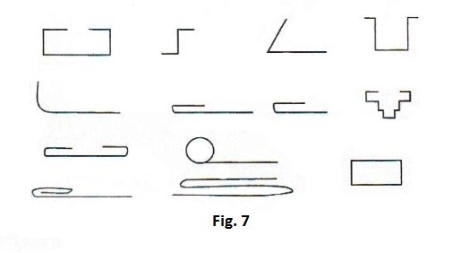
The top beam comes in two types of blades: 35° and 55°. The 55° blade is a segmented blade that can be assembled into blades of varying lengths to accommodate boxes of different shapes.
A typical example is shown in Figure 7.
Reasonable use and maintenance
Before using the machine, it is important to carefully inspect the blade clearance, as shown in Figure 2 (S valve). It is strictly forbidden to bend too large plates, as this may damage the blade.
It is recommended to use the machine at a moderate pace. No one should be behind the balance hammer to avoid possible accidents.
Regular attention should also be paid to bearing and lubrication positions.