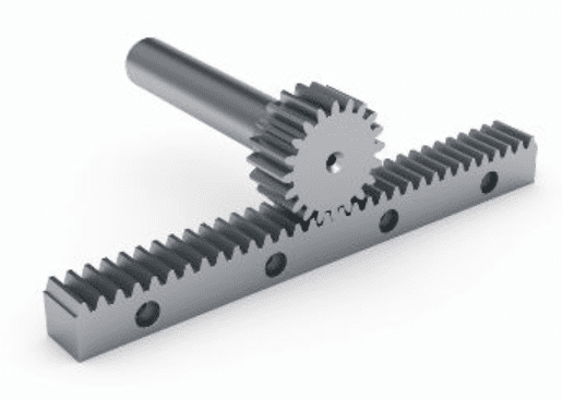
In linear motion applications, ball screws are widely recognized for their ability to provide high thrust forces, while linear motors are gaining market share in high-speed applications and belt drives continue to maintain their reputation as the best solution for long journeys. But rack and pinion drives are often overlooked workhorses in conveyor and gantry applications that require long travel, high acceleration rates and high thrust forces at a relatively low cost – a price-performance combination that other drive technologies have difficulty achieving.
Although rack and pinion transmission is sometimes considered an old technology, an analysis of the linear motion solutions market shows that this is not the case. In fact, linear actuator manufacturers often offer rack and pinion drive versions, and several profiled rail guide manufacturers offer integrated rack and pinion systems, with the rack grounded in the guide profile or the guide mounted directly to the rack.
Further proof that rack and pinion transmissions are not going away is the investment manufacturers continue to make in technology, from developing improved methods for grinding teeth to discovering new materials with improved hardness and surface finish for less wear. greater efficiency and weight reduction. .
Unlike ball screw assemblies, rack and pinion drives can provide high speeds and high thrust forces regardless of length or mounting factors.
This is good news for designers and engineers facing applications that require any combination of long stroke, high thrust force, high speed and harsh environmental conditions. And compared to other linear drive options, rack and pinion drives are relatively simple to select, integrate and operate.
Case in point: Unlike ball screw sizing, which must take into account factors such as characteristic and critical speeds, end bearing considerations and preload effects, in addition to basic thrust force and drive torque calculations, the Rack transmission sizing is based mainly on three factors: the force perceived by the rack (indicated as “feed force” or “tangential force”), the torque perceived by the pinion and the rotational speed of the pinion.
Tangential force on the rack: horizontal application
In a horizontal application, the rack suffers two forces due to the movement of the mass: a force created due to the displaced mass acting against the friction coefficient of the guides, plus a force that results from the acceleration of the mass. Furthermore, if the application involves external pressure forces, these will be included in the tangential force calculation.
![]()
F R = force on the rack (N, lbf)
m = mass moved; includes the application load, plus any system components that are moved, such as pinion, gearbox, motor, etc. (kg, lbm)
g = gravitational constant (9.81 m/s 2 32.2 ft/s 2 )
μ = coefficient of friction of the guide mechanism (typically 0.002 to 0.003 for ball guides or recirculating rollers)
a = maximum acceleration that the system will undergo (m/s 2 ft/s 2 )
F E = pressure force due to application; if applicable (N, lbf)
Tangential force on the rack: vertical application
In a vertical application, the load moves in the direction of the guide system, so that the force due to the displaced mass is not affected by the friction coefficient of the guides.
![]()
Torque on the pinion
Pinion torque is simply the tangential force (rack force) divided by the pinion radius.
![]()
T p = pinion torque (Nm, ft-lb)
R p = pinion radius (m, feet)
Maximum pinion rotation speed
To determine the maximum pinion rotation speed, simply divide the maximum linear speed of your application by the pinion circumference (π * diameter), convert from millimeters to meters and convert from seconds (linear speed, m/s or feet/s) to minutes (rotation speed, rpm).
![]() n p = maximum pinion rotation speed (rpm)
n p = maximum pinion rotation speed (rpm)
v max. = maximum linear speed of the application (m/s, ft/s)
It is important to note that rack and pinion manufacturers recommend using several “correction” factors to determine the force on the rack. The most common are a typical safety factor and a service factor (sometimes called a “load factor” or “operating mode factor”), which is determined by the level of shock loads that the pinion drive and the rack can find. Some manufacturers also recommend taking into account a service life factor, depending on pinion speed and lubrication frequency (continuous, daily or monthly).
In addition to mechanical sizing, selecting a suitable rack and pinion drive for an application also includes determining the gear quality, surface treatment and hardness required. Although surface treatment and hardness are relatively simple, gear quality is a rating system that specifies allowable values for gear flank tolerances (which play a significant role in positioning accuracy and smoothness of speed and force production). ). Gear quality is defined in several standards, including the ANSI/AGMA 2015-2 standard and the ISO 1328-1 standard.