How to calculate the radius of curvature of sheet metal?
Sheet metal bending radius is a critical value in sheet metal drawing that can be difficult to determine during actual processing.
This radius depends on the thickness of the material, the pressure of the bending machine and the width of the bottom groove of the bending die.
A simple and approximate method to determine the radius of curvature is:
- If the plate thickness is less than 6mm, the bending radius can be equal to the plate thickness.
- If the plate thickness is between 6mm and 12mm, the bending radius is typically 1.25 to 1.5 times the plate thickness.
- If the plate thickness is greater than or equal to 12 mm, the bending radius is normally 2 to 3 times the plate thickness.
Experience in actual sheet metal processing shows that when the thickness of the plate is generally not more than 6mm, the inner bending radius of the sheet metal can directly use the plate thickness as the radius.
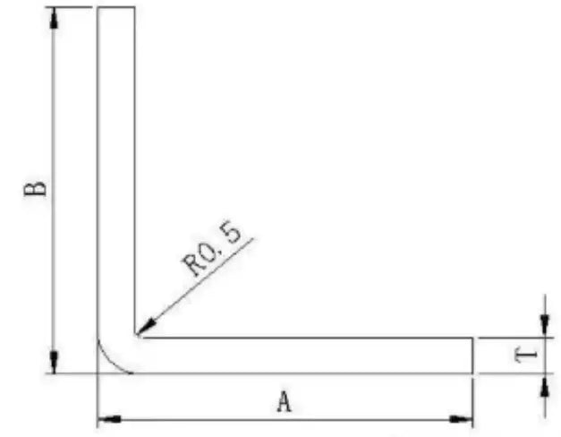
When the radius of curvature is r = 0.5, the overall thickness of the metal sheet t is equal to 0.5 mm.

If a bending radius different from the board thickness is required, a special die must be used for processing.
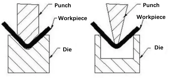
When the sheet metal design requires a 90-degree bend with a particularly small bending radius, the sheet metal must first be grooved and then bent.
Special press brake tools such as punches and dies can also be used.
The relationship between the radius of curvature of sheet metal and the width of the bottom groove of the bending die has been established through numerous experiments in sheet metal processing.
For example, when a 1.0mm board is bent with a groove width of 8mm, the ideal bending radius is R1.
If the groove width is increased to 20 mm, the depth of the stretched plate increases, resulting in a larger pull area and a larger R angle.
To avoid damage to the press brake die and maintain the desired bending radius, it is recommended to bend with a narrow channel, following the standard ratio of 1:8 between plate thickness and channel width.
The minimum recommended ratio is 1:6 and doubling with a ratio less than 1:4 is not recommended.
Suggestion: If resistance allows, it is preferable to first groove and then bend to obtain a small radius of curvature of the sheet.
The following figure is a table provided by the press brake manufacturer, which shows the corresponding relationship between bending radius, pressure and minimum bending height.
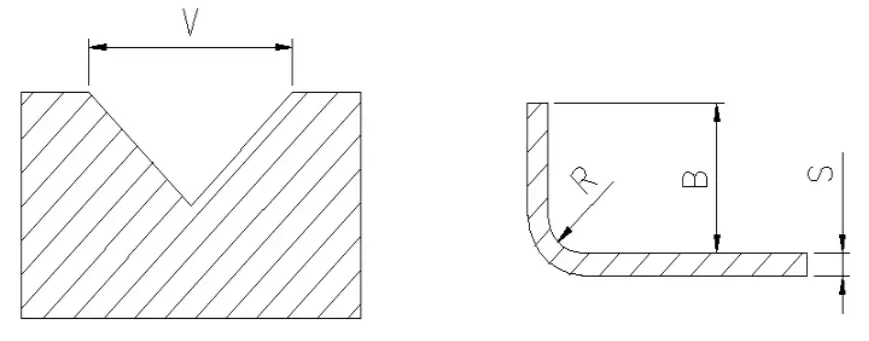
- V – bend notch width
- R – radius of curvature
- B – minimum flexion height
- S – sheet thickness
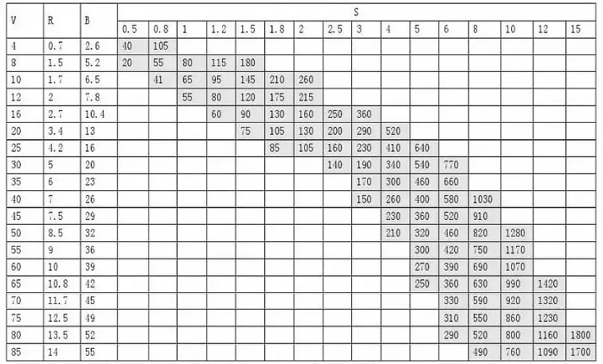
Note: The grayscale data in the table represents the required bending pressure P (KN/m), and the maximum bending force of the press brake is 1700KN. There are five bending edges available: V = 12, 16, 25, 40 and 50.
Consult the available knife edge and bend length to determine the bend radius, which will help you calculate the precise length of the material to be unfolded.
The above information refers to the bending die pressure and width parameters of a single press brake.
Actual calculations should be based on the pressure and bending die of your own sheet metal processing facility.
Bend radius chart for mild steel, stainless steel and aluminum
When considering sheet metal design, it is important to understand how the radius of curvature affects the choice of materials. In this section, we will discuss some popular material options, such as mild steel, stainless steel, and aluminum alloys.
(1) Bend radius chart for mild steel
Carbon steel is a versatile material for manufacturing sheet metal due to its formability and economy. When bending low-carbon steel, you should aim for a minimum bend radius equal to or greater than the sheet thickness. Some common thicknesses and their respective minimum bend radii include:
| Thickness | Minimum Curvature | radius of curvature |
| (0.02″ 0.51mm) | 0.75″ 19.05mm | 0.605″ 15.37mm |
| (0.02″ 0.51mm) | 0.2″ 5.08mm | 0.05″ 1.27mm |
| (0.03″ 0.76mm) | 0.2″ 5.08mm | 0.05″ 1.27mm |
| (0.25″ 6.35mm) | 1.375″ 34.92mm | 0.17″ 4.32mm |
| (0.25″ 6.35mm) | 1.375″ 34.92mm | 0.25″ 6.35mm |
| (0.25″ 6.35mm) | 1.5″ 38.10mm | 0.35″ 8.89mm |
| (0.25″ 6.35mm) | 1.5″ 38.10mm | 0.25″ 6.35mm |
| 11 Gauge (0.12″ 3.05mm) | 1.375″ 34.92mm | 0.375″ 9.52mm |
| 11 Gauge (0.12″ 3.05mm) | 0.75″ 19.05mm | 0.16″ 4.06mm |
| 11 Gauge (0.12″ 3.05mm) | 0.5″ 12.70mm | 0.115″ 2.92mm |
| 11 Gauge (0.12″ 3.05mm) | 0.5″ 12.70mm | 0.085″ 2.16mm |
| 11 Gauge (0.12″ 3.05mm) | 0.5″ 12.70mm | 0.06″ 1.52mm |
| 11 Gauge (0.12″ 3.05mm) | 0.5″ 12.70mm | 0.06″ 1.52mm |
| 11 Gauge (0.12″ 3.05mm) | 0.5″ 12.70mm | 0.045″ 1.14mm |
| 12 Gauge (0.105″ 2.67mm) | 0.5″ 12.70mm | 0.085″ 2.16mm |
| 12 Gauge (0.105″ 2.67mm) | 0.5″ 12.70mm | 0.07″ 1.78mm |
| 12 Gauge (0.105″ 2.67mm) | 0.5″ 12.70mm | 0.065″ 1.65mm |
| 12 Gauge (0.105″ 2.67mm) | 0.5″ 12.70mm | 0.05″ 1.27mm |
| 13 Gauge (0.09″ 2.29mm) | 0.375″ 9.52mm | 0.045″ 1.14mm |
| 13 Gauge (0.09″ 2.29mm) | 0.375″ 9.52mm | 0.04″ 1.02mm |
| 13 Gauge (0.09″ 2.29mm) | 1.375″ 34.92mm | 0.28″ 7.11mm |
| 13 Gauge (0.09″ 2.29mm) | 0.375″ 9.52mm | 0.055″ 1.40mm |
| 13 Gauge (0.09″ 2.29mm) | 0.5″ 12.70mm | 0.065″ 1.65mm |
| 13 Gauge (0.09″ 2.29mm) | 0.5″ 12.70mm | 0.08″ 2.03mm |
| 13 Gauge (0.09″ 2.29mm) | 0.5″ 12.70mm | 0.075″ 1.90mm |
| 13 Gauge (0.09″ 2.29mm) | 0.375″ 9.52mm | 0.06″ 1.52mm |
| 13 Gauge (0.09″ 2.29mm) | 0.375″ 9.52mm | 0.05″ 1.27mm |
| 13 Gauge (0.09″ 2.29mm) | 1.375″ 34.92mm | 0.375″ 9.52mm |
| 13 Gauge (0.09″ 2.29mm) | 0.5″ 12.70mm | 0.08″ 2.03mm |
| 13 Gauge (0.09″ 2.29mm) | 0.5″ 12.70mm | 0.06″ 1.52mm |
| 14 Gauge (0.075″ 1.90mm) | 0.375″ 9.52mm | 0.04″ 1.02mm |
| 14 Gauge (0.075″ 1.90mm) | 0.3″ 7.62mm | 0.062″ 1.57mm |
| 14 Gauge (0.075″ 1.90mm) | 1.375″ 34.92mm | 0.375″ 9.52mm |
| 14 Gauge (0.075″ 1.90mm) | 0.275″ 6.98mm | 0.062″ 1.57mm |
| 14 Gauge (0.075″ 1.90mm) | 0.3″ 7.62mm | 0.04″ 1.02mm |
| 14 Gauge (0.075″ 1.90mm) | 0.3″ 7.62mm | 0.06″ 1.52mm |
| 14 Gauge (0.075″ 1.90mm) | 0.5″ 12.70mm | 0.08″ 2.03mm |
| 14 Gauge (0.075″ 1.90mm) | 0.375″ 9.52mm | 0.06″ 1.52mm |
| 14 Gauge (0.075″ 1.90mm) | 0.3″ 7.62mm | 0.045″ 1.14mm |
| 14 Gauge (0.075″ 1.90mm) | 0.3″ 7.62mm | 0.055″ 1.40mm |
| 14 Gauge (0.075″ 1.90mm) | 0.5″ 12.70mm | 0.1″ 2.54mm |
| 14 Gauge (0.075″ 1.90mm) | 0.5″ 12.70mm | 0.125″ 3.18mm |
| 16 Gauge (0.06″ 1.52mm) | 0.2″ 5.08mm | 0.045″ 1.14mm |
| 16 Gauge (0.06″ 1.52mm) | 0.3″ 7.62mm | 0.06″ 1.52mm |
| 16 Gauge (0.06″ 1.52mm) | 1.5″ 38.10mm | 0.995″ 25.27mm |
| 16 Gauge (0.06″ 1.52mm) | 0.375″ 9.52mm | 0.075″ 1.90mm |
| 16 Gauge (0.06″ 1.52mm) | 0.2″ 5.08mm | 0.04″ 1.02mm |
| 16 Gauge (0.06″ 1.52mm) | 0.265″ 6.73mm | 0.05″ 1.27mm |
| 16 Gauge (0.06″ 1.52mm) | 0.5″ 12.70mm | 0.24″ 6.10mm |
| 16 Gauge (0.06″ 1.52mm) | 0.265″ 6.73mm | 0.055″ 1.40mm |
| 16 Gauge (0.06″ 1.52mm) | 0.265″ 6.73mm | 0.062″ 1.57mm |
| 16 Gauge (0.06″ 1.52mm) | 0.375″ 9.52mm | 0.065″ 1.65mm |
| 16 Gauge (0.06″ 1.52mm) | 0.5″ 12.70mm | 0.08″ 2.03mm |
| 16 Gauge (0.06″ 1.52mm) | 0.3″ 7.62mm | 0.055″ 1.40mm |
| 16 Gauge (0.06″ 1.52mm) | 0.5″ 12.70mm | 0.125″ 3.18mm |
| 16 Gauge (0.06″ 1.52mm) | 1.5″ 38.10mm | 0.985″ 25.02mm |
| 16 Gauge (0.06″ 1.52mm) | 0.55″ 13.97mm | 0.03″ 0.76mm |
| 16 Gauge (0.06″ 1.52mm) | 0.3″ 7.62mm | 0.062″ 1.57mm |
| 16 Gauge (0.06″ 1.52mm) | 1.375″ 34.92mm | 0.375″ 9.52mm |
| 18 Gauge (0.048″ 1.22mm) | 0.3″ 7.62mm | 0.06″ 1.52mm |
| 18 Gauge (0.048″ 1.22mm) | 0.265″ 6.73mm | 0.05″ 1.27mm |
| 18 Gauge (0.048″ 1.22mm) | 0.2″ 5.08mm | 0.03″ 0.76mm |
| 18 Gauge (0.048″ 1.22mm) | 0.375″ 9.52mm | 0.05″ 1.27mm |
| 18 Gauge (0.048″ 1.22mm) | 0.265″ 6.73mm | 0.065″ 1.65mm |
| 18 Gauge (0.048″ 1.22mm) | 0.2″ 5.08mm | 0.04″ 1.02mm |
| 18 Gauge (0.048″ 1.22mm) | 1.5″ 38.10mm | 1.1″ 27.94mm |
| 18 Gauge (0.048″ 1.22mm) | 0.375″ 9.52mm | 0.125″ 3.18mm |
| 18 Gauge (0.048″ 1.22mm) | 0.55″ 13.97mm | 0.03″ 0.76mm |
| 18 Gauge (0.048″ 1.22mm) | 0.265″ 6.73mm | 0.062″ 1.57mm |
| 18 Gauge (0.048″ 1.22mm) | 0.2″ 5.08mm | 0.045″ 1.14mm |
| 18 Gauge (0.048″ 1.22mm) | 0.5″ 12.70mm | 0.12″ 3.05mm |
| 18 Gauge (0.048″ 1.22mm) | 0.3″ 7.62mm | 0.04″ 1.02mm |
| 18 Gauge (0.048″ 1.22mm) | 1.375″ 34.92mm | 0.375″ 9.52mm |
| 18 Gauge (0.048″ 1.22mm) | 0.5″ 12.70mm | 0.105″ 2.67mm |
| 20 Gauge (0.036″ 0.91mm) | 0.5″ 12.70mm | 0.11″ 2.79mm |
| 20 Gauge (0.036″ 0.91mm) | 0.265″ 6.73mm | 0.055″ 1.40mm |
| 20 Gauge (0.036″ 0.91mm) | 0.2″ 5.08mm | 0.05″ 1.27mm |
| 20 Gauge (0.036″ 0.91mm) | 0.2″ 5.08mm | 0.04″ 1.02mm |
| 20 Gauge (0.036″ 0.91mm) | 0.2″ 5.08mm | 0.035″ 0.89mm |
| 20 Gauge (0.036″ 0.91mm) | 0.375″ 9.52mm | 0.07″ 1.78mm |
| 20 Gauge (0.036″ 0.91mm) | 0.55″ 13.97mm | 0.03″ 0.76mm |
| 20 Gauge (0.036″ 0.91mm) | 0.265″ 6.73mm | 0.065″ 1.65mm |
| 20 Gauge (0.036″ 0.91mm) | 1.375″ 34.92mm | 0.375″ 9.52mm |
| 22 Gauge (0.03″ 0.76mm) | 0.5″ 12.70mm | 0.09″ 2.29mm |
| 22 Gauge (0.03″ 0.76mm) | 0.2″ 5.08mm | 0.05″ 1.27mm |
| 22 Gauge (0.03″ 0.76mm) | 0.2″ 5.08mm | 0.04″ 1.02mm |
| 22 Gauge (0.03″ 0.76mm) | 0.265″ 6.73mm | 0.055″ 1.40mm |
| 22 Gauge (0.03″ 0.76mm) | 0.265″ 6.73mm | 0.065″ 1.65mm |
| 22 Gauge (0.03″ 0.76mm) | 0″ 0.00mm | 0.025″ 0.64mm |
| 22 Gauge (0.03″ 0.76mm) | 0.265″ 6.73mm | 0.07″ 1.78mm |
| 22 Gauge (0.03″ 0.76mm) | 0.375″ 9.52mm | 0.085″ 2.16mm |
Keep in mind that tighter folds may cause the material to crack or distort. Thicker sheets may also require greater force during the bending process.
(2) Bend radius chart for stainless steel
Stainless steel is known for its corrosion resistance and durability. For most types of stainless steel, you will need a larger bend radius compared to low carbon steel. The relationship between the radius of curvature and the thickness of the sheet typically varies between 1:1 and 2:1, depending on factors such as the type, hardness and thickness of the stainless steel. Some guidelines for minimum bend radii include:
| Thickness | Minimum Curvature | radius of curvature |
| (0.12″ 3.05mm) | 0.75″ 19.05mm | 0.22″ 5.59mm |
| (0.12″ 3.05mm) | 1.5″ 38.10mm | 1.05″ 26.67mm |
| (0.12″ 3.05mm) | 0.75″ 19.05mm | 0.2″ 5.08mm |
| (0.125″ 3.18mm) | 0.5″ 12.70mm | 0.09″ 2.29mm |
| (0.125″ 3.18mm) | 0.5″ 12.70mm | 0.08″ 2.03mm |
| (0.125″ 3.18mm) | 0.5″ 12.70mm | 0.125″ 3.18mm |
| (0.125″ 3.18mm) | 0.5″ 12.70mm | 0.1″ 2.54mm |
| 12 Gauge (0.109″ 2.77mm) | 0.5″ 12.70mm | 0.06″ 1.52mm |
| 12 Gauge (0.109″ 2.77mm) | 0.5″ 12.70mm | 0.095″ 2.41mm |
| 12 Gauge (0.109″ 2.77mm) | 0.75″ 19.05mm | 0.18″ 4.57mm |
| 12 Gauge (0.109″ 2.77mm) | 0.5″ 12.70mm | 0.095″ 2.41mm |
| 12 Gauge (0.109″ 2.77mm) | 0.75″ 19.05mm | 0.22″ 5.59mm |
| 14 Gauge (0.078″ 1.98mm) | 0.275″ 6.98mm | 0.062″ 1.57mm |
| 14 Gauge (0.078″ 1.98mm) | 1.375″ 34.92mm | 0.4″ 10.16mm |
| 14 Gauge (0.078″ 1.98mm) | 0.3″ 7.62mm | 0.05″ 1.27mm |
| 14 Gauge (0.078″ 1.98mm) | 0.275″ 6.98mm | 0.075″ 1.90mm |
| 14 Gauge (0.078″ 1.98mm) | 0.375″ 9.52mm | 0.07″ 1.78mm |
| 14 Gauge (0.078″ 1.98mm) | 0.5″ 12.70mm | 0.11″ 2.79mm |
| 14 Gauge (0.078″ 1.98mm) | 0.5″ 12.70mm | 0.12″ 3.05mm |
| 14 Gauge (0.078″ 1.98mm) | 0.5″ 12.70mm | 0.13″ 3.30mm |
| 14 Gauge (0.078″ 1.98mm) | 0.5″ 12.70mm | 0.09″ 2.29mm |
| 14 Gauge (0.078″ 1.98mm) | 0.275″ 6.98mm | 0.05″ 1.27mm |
| 14 Gauge (0.078″ 1.98mm) | 0.5″ 12.70mm | 0.115″ 2.92mm |
| 14 Gauge (0.078″ 1.98mm) | 0.75″ 19.05mm | 0.26″ 6.60mm |
| 14 Gauge (0.078″ 1.98mm) | 0.375″ 9.52mm | 0.105″ 2.67mm |
| 14 Gauge (0.078″ 1.98mm) | 1.5″ 38.10mm | 1.125″ 28.58mm |
| 14 Gauge (0.078″ 1.98mm) | 0.3″ 7.62mm | 0.055″ 1.40mm |
| 16 Gauge (0.063″ 1.60mm) | 0.5″ 12.70mm | 0.25″ 6.35mm |
| 16 Gauge (0.063″ 1.60mm) | 0.5″ 12.70mm | 0.04″ 1.02mm |
| 16 Gauge (0.063″ 1.60mm) | 0.2″ 5.08mm | 0.04″ 1.02mm |
| 16 Gauge (0.063″ 1.60mm) | 0.3″ 7.62mm | 0.05″ 1.27mm |
| 16 Gauge (0.063″ 1.60mm) | 0.5″ 12.70mm | 0.12″ 3.05mm |
| 16 Gauge (0.063″ 1.60mm) | 0.3″ 7.62mm | 0.055″ 1.40mm |
| 16 Gauge (0.063″ 1.60mm) | 0.3″ 7.62mm | 0.08″ 2.03mm |
| 16 Gauge (0.063″ 1.60mm) | 0.265″ 6.73mm | 0.055″ 1.40mm |
| 16 Gauge (0.063″ 1.60mm) | 0.375″ 9.52mm | 0.07″ 1.78mm |
| 16 Gauge (0.063″ 1.60mm) | 0.2″ 5.08mm | 0.05″ 1.27mm |
| 16 Gauge (0.063″ 1.60mm) | 0.265″ 6.73mm | 0.075″ 1.90mm |
| 16 Gauge (0.063″ 1.60mm) | 0.2″ 5.08mm | 0.05″ 1.27mm |
| 16 Gauge (0.063″ 1.60mm) | 0.265″ 6.73mm | 0.08″ 2.03mm |
| 16 Gauge (0.063″ 1.60mm) | 0.5″ 12.70mm | 0.1″ 2.54mm |
| 16 Gauge (0.063″ 1.60mm) | 0.2″ 5.08mm | 0.035″ 0.89mm |
| 16 Gauge (0.063″ 1.60mm) | 0.5″ 12.70mm | 0.105″ 2.67mm |
| 18 Gauge (0.05″ 1.27mm) | 0.2″ 5.08mm | 0.05″ 1.27mm |
| 18 Gauge (0.05″ 1.27mm) | 0.5″ 12.70mm | 0.04″ 1.02mm |
| 18 Gauge (0.05″ 1.27mm) | 0.5″ 12.70mm | 0.12″ 3.05mm |
| 18 Gauge (0.05″ 1.27mm) | 0.5″ 12.70mm | 0.115″ 2.92mm |
| 18 Gauge (0.05″ 1.27mm) | 0.3″ 7.62mm | 0.07″ 1.78mm |
| 18 Gauge (0.05″ 1.27mm) | 0.375″ 9.52mm | 0.1″ 2.54mm |
| 18 Gauge (0.05″ 1.27mm) | 0.3″ 7.62mm | 0.06″ 1.52mm |
| 18 Gauge (0.05″ 1.27mm) | 0.2″ 5.08mm | 0.045″ 1.14mm |
| 18 Gauge (0.05″ 1.27mm) | 0.265″ 6.73mm | 0.08″ 2.03mm |
| 18 Gauge (0.05″ 1.27mm) | 0.5″ 12.70mm | 0.12″ 3.05mm |
| 18 Gauge (0.05″ 1.27mm) | 0.375″ 9.52mm | 0.125″ 3.18mm |
| 18 Gauge (0.05″ 1.27mm) | 0.5″ 12.70mm | 0.24″ 6.10mm |
| 18 Gauge (0.05″ 1.27mm) | 0.265″ 6.73mm | 0.085″ 2.16mm |
| 18 Gauge (0.05″ 1.27mm) | 1.375″ 34.92mm | 0.4″ 10.16mm |
| 18 Gauge (0.05″ 1.27mm) | 0.2″ 5.08mm | 0.04″ 1.02mm |
| 18 Gauge (0.05″ 1.27mm) | 0.265″ 6.73mm | 0.06″ 1.52mm |
| 18 Gauge (0.05″ 1.27mm) | 0.375″ 9.52mm | 0.09″ 2.29mm |
| 18 Gauge (0.05″ 1.27mm) | 0.3″ 7.62mm | 0.08″ 2.03mm |
| 20 Gauge (0.038″ 0.97mm) | 0.3″ 7.62mm | 0.06″ 1.52mm |
| 20 Gauge (0.038″ 0.97mm) | 0.5″ 12.70mm | 0.125″ 3.18mm |
| 20 Gauge (0.038″ 0.97mm) | 0.5″ 12.70mm | 0.11″ 2.79mm |
| 20 Gauge (0.038″ 0.97mm) | 0.5″ 12.70mm | 0.1″ 2.54mm |
| 20 Gauge (0.038″ 0.97mm) | 0.375″ 9.52mm | 0.095″ 2.41mm |
| 20 Gauge (0.038″ 0.97mm) | 0.2″ 5.08mm | 0.05″ 1.27mm |
| 20 Gauge (0.038″ 0.97mm) | 0.3″ 7.62mm | 0.07″ 1.78mm |
| 20 Gauge (0.038″ 0.97mm) | 0.265″ 6.73mm | 0.07″ 1.78mm |
| 20 Gauge (0.038″ 0.97mm) | 0.5″ 12.70mm | 0.4″ 10.16mm |
| 22 Gauge (0.031″ 0.79mm) | 0.55″ 13.97mm | 0.03″ 0.76mm |
| 22 Gauge (0.031″ 0.79mm) | 0.265″ 6.73mm | 0.08″ 2.03mm |
| 22 Gauge (0.031″ 0.79mm) | 0.375″ 9.52mm | 0.08″ 2.03mm |
| 22 Gauge (0.031″ 0.79mm) | 0.3″ 7.62mm | 0.08″ 2.03mm |
| 22 Gauge (0.031″ 0.79mm) | 0.5″ 12.70mm | 0.09″ 2.29mm |
| 22 Gauge (0.031″ 0.79mm) | 0.3″ 7.62mm | 0.075″ 1.90mm |
| 22 Gauge (0.031″ 0.79mm) | 0.2″ 5.08mm | 0.04″ 1.02mm |
| 22 Gauge (0.031″ 0.79mm) | 0.2″ 5.08mm | 0.05″ 1.27mm |
| 24 Gauge (0.024″ 0.61mm) | 0.2″ 5.08mm | 0.04″ 1.02mm |
| 24 Gauge (0.024″ 0.61mm) | 0.265″ 6.73mm | 0.08″ 2.03mm |
| 24 gauge (0.025″ 0.64mm) | 0.5″ 12.70mm | 0.1″ 2.54mm |
Remember to consider the type and properties of the stainless steel you choose when determining the appropriate bend radius for your application.
(3) Bend radius chart for aluminum alloys
Aluminum alloys offer lightweight, strong, and corrosion-resistant options for sheet metal fabrication. Similar to low-carbon steel, the minimum bend radius for aluminum alloys is typically equal to the sheet thickness. However, some specific alloys may have better or worse formability. Here is a general guide to minimum bend radii for some popular aluminum alloys:
| Thickness | Minimum Curvature | radius of curvature |
| (0.032″ 0.81mm) | 0.2″ 5.08mm | 0.04″ 1.02mm |
| (0.032″ 0.81mm) | 0.2″ 5.08mm | 0.035″ 0.89mm |
| (0.1285″ 3.26mm) | 1.375″ 34.92mm | 0.375″ 9.52mm |
| (0.25″ 6.35mm) | 1.375″ 34.92mm | 0.16″ 4.06mm |
| (0.25″ 6.35mm) | 1.375″ 34.92mm | 0.375″ 9.52mm |
| (0.25″ 6.35mm) | 0.75″ 19.05mm | 0.125″ 3.18mm |
| 10 Gauge (0.102″ 2.59mm) | 0.5″ 12.70mm | 0.078″ 1.98mm |
| 10 Gauge (0.102″ 2.59mm) | 0.5″ 12.70mm | 0.045″ 1.14mm |
| 10 Gauge (0.102″ 2.59mm) | 0.5″ 12.70mm | 0.125″ 3.18mm |
| 10 Gauge (0.102″ 2.59mm) | 1.5″ 38.10mm | 1.063″ 27.00mm |
| 10 Gauge (0.102″ 2.59mm) | 0.5″ 12.70mm | 0.04″ 1.02mm |
| 10 Gauge (0.102″ 2.59mm) | 1.5″ 38.10mm | 1.125″ 28.58mm |
| 10 Gauge (0.102″ 2.59mm) | 0.5″ 12.70mm | 0.04″ 1.02mm |
| 10 Gauge (0.102″ 2.59mm) | 0.5″ 12.70mm | 0.07″ 1.78mm |
| 11 Gauge (0.091″ 2.31mm) | 0.5″ 12.70mm | 0.05″ 1.27mm |
| 11 Gauge (0.091″ 2.31mm) | 0.75″ 19.05mm | 0.24″ 6.10mm |
| 11 Gauge (0.091″ 2.31mm) | 0.375″ 9.52mm | 0.04″ 1.02mm |
| 11 Gauge (0.091″ 2.31mm) | 0.375″ 9.52mm | 0.04″ 1.02mm |
| 11 Gauge (0.091″ 2.31mm) | 1.375″ 34.92mm | 0.24″ 6.10mm |
| 11 Gauge (0.091″ 2.31mm) | 1.375″ 34.92mm | 0.375″ 9.52mm |
| 11 Gauge (0.091″ 2.31mm) | 0.375″ 9.52mm | 0.05″ 1.27mm |
| 11 Gauge (0.091″ 2.31mm) | 0.5″ 12.70mm | 0.045″ 1.14mm |
| 11 Gauge (0.091″ 2.31mm) | 0.5″ 12.70mm | 0.125″ 3.18mm |
| 11 Gauge (0.091″ 2.31mm) | 0.375″ 9.52mm | 0.062″ 1.57mm |
| 11 Gauge (0.091″ 2.31mm) | 0.5″ 12.70mm | 0.05″ 1.27mm |
| 11 Gauge (0.091″ 2.31mm) | 0.375″ 9.52mm | 0.045″ 1.14mm |
| 11 Gauge (0.091″ 2.31mm) | 0.5″ 12.70mm | 0.04″ 1.02mm |
| 11 Gauge (0.0914″ 2.32mm) | 0.375″ 9.52mm | 0.04″ 1.02mm |
| 12 Gauge (0.081″ 2.06mm) | 0.3″ 7.62mm | 0.0622″ 1.58mm |
| 12 Gauge (0.081″ 2.06mm) | 0.5″ 12.70mm | 0.045″ 1.14mm |
| 12 Gauge (0.081″ 2.06mm) | 0.375″ 9.52mm | 0.04″ 1.02mm |
| 12 Gauge (0.081″ 2.06mm) | 0.5″ 12.70mm | 0.04″ 1.02mm |
| 12 Gauge (0.081″ 2.06mm) | 1.375″ 34.92mm | 0.375″ 9.52mm |
| 12 Gauge (0.081″ 2.06mm) | 1.5″ 38.10mm | 1.1″ 27.94mm |
| 12 Gauge (0.081″ 2.06mm) | 1.5″ 38.10mm | 1″ 25.40mm |
| 12 Gauge (0.081″ 2.06mm) | 0.275″ 6.98mm | 0.04″ 1.02mm |
| 12 Gauge (0.081″ 2.06mm) | 0.5″ 12.70mm | 0.125″ 3.18mm |
| 12 Gauge (0.081″ 2.06mm) | 0.3″ 7.62mm | 0.04″ 1.02mm |
| 12 Gauge (0.081″ 2.06mm) | 0.5″ 12.70mm | 0.055″ 1.40mm |
| 12 Gauge (0.081″ 2.06mm) | 0.275″ 6.98mm | 0.062″ 1.57mm |
| 12 Gauge (0.081″ 2.06mm) | 0.75″ 19.05mm | 0.24″ 6.10mm |
| 14 Gauge (0.064″ 1.63mm) | 1.5″ 38.10mm | 1.2″ 30.48mm |
| 14 Gauge (0.064″ 1.63mm) | 0.3″ 7.62mm | 0.035″ 0.89mm |
| 14 Gauge (0.064″ 1.63mm) | 0.55″ 13.97mm | 0.03″ 0.76mm |
| 14 Gauge (0.064″ 1.63mm) | 1.375″ 34.92mm | 0.375″ 9.52mm |
| 14 Gauge (0.064″ 1.63mm) | 0.265″ 6.73mm | 0.04″ 1.02mm |
| 14 Gauge (0.064″ 1.63mm) | 0.265″ 6.73mm | 0.035″ 0.89mm |
| 14 Gauge (0.064″ 1.63mm) | 0.3″ 7.62mm | 0.04″ 1.02mm |
| 14 Gauge (0.064″ 1.63mm) | 0.5″ 12.70mm | 0.125″ 3.18mm |
| 14 Gauge (0.064″ 1.63mm) | 1.5″ 38.10mm | 0.7″ 17.78mm |
| 14 Gauge (0.064″ 1.63mm) | 0.3″ 7.62mm | 0.062″ 1.57mm |
| 14 Gauge (0.064″ 1.63mm) | 0.2″ 5.08mm | 0.045″ 1.14mm |
| 14 Gauge (0.064″ 1.63mm) | 0.2″ 5.08mm | 0.035″ 0.89mm |
| 14 Gauge (0.064″ 1.63mm) | 1.5″ 38.10mm | 1.225″ 31.12mm |
| 14 Gauge (0.064″ 1.63mm) | 0.375″ 9.52mm | 0.06″ 1.52mm |
| 14 Gauge (0.064″ 1.63mm) | 0.5″ 12.70mm | 0.22″ 5.59mm |
| 14 Gauge (0.064″ 1.63mm) | 0.5″ 12.70mm | 0.045″ 1.14mm |
| 14 Gauge (0.064″ 1.63mm) | 0.375″ 9.52mm | 0.04″ 1.02mm |
| 14 Gauge (0.064″ 1.63mm) | 0.5″ 12.70mm | 0.05″ 1.27mm |
| 14 Gauge (0.064″ 1.63mm) | 0.2″ 5.08mm | 0.04″ 1.02mm |
| 14 Gauge (0.064″ 1.63mm) | 0.265″ 6.73mm | 0.062″ 1.57mm |
| 14 Gauge (0.064″ 1.63mm) | 0.5″ 12.70mm | 0.04″ 1.02mm |
| 14 Gauge (0.064″ 1.63mm) | 0.2″ 5.08mm | 0.035″ 0.89mm |
| 14 Gauge (0.064″ 1.63mm) | 1.5″ 38.10mm | 1.13″ 28.70mm |
| 16 Gauge (0.051″ 1.30mm) | 1.5″ 38.10mm | 1.2″ 30.48mm |
| 16 Gauge (0.051″ 1.30mm) | 0.375″ 9.52mm | 0.04″ 1.02mm |
| 16 Gauge (0.051″ 1.30mm) | 0.265″ 6.73mm | 0.035″ 0.89mm |
| 16 Gauge (0.051″ 1.30mm) | 0.3″ 7.62mm | 0.04″ 1.02mm |
| 16 Gauge (0.051″ 1.30mm) | 0.5″ 12.70mm | 0.125″ 3.18mm |
| 16 Gauge (0.051″ 1.30mm) | 0.3″ 7.62mm | 0.062″ 1.57mm |
| 16 Gauge (0.051″ 1.30mm) | 0.55″ 13.97mm | 0.03″ 0.76mm |
| 16 Gauge (0.051″ 1.30mm) | 0.5″ 12.70mm | 0.23″ 5.84mm |
| 16 Gauge (0.051″ 1.30mm) | 0.2″ 5.08mm | 0.035″ 0.89mm |
| 16 Gauge (0.051″ 1.30mm) | 0.5″ 12.70mm | 0.04″ 1.02mm |
| 16 Gauge (0.051″ 1.30mm) | 0.2″ 5.08mm | 0.045″ 1.14mm |
| 16 Gauge (0.051″ 1.30mm) | 0.375″ 9.52mm | 0.05″ 1.27mm |
| 16 Gauge (0.051″ 1.30mm) | 0.265″ 6.73mm | 0.05″ 1.27mm |
| 16 Gauge (0.051″ 1.30mm) | 0.5″ 12.70mm | 0.05″ 1.27mm |
| 16 Gauge (0.051″ 1.30mm) | 1.375″ 34.92mm | 0.4″ 10.16mm |
| 16 Gauge (0.051″ 1.30mm) | 0.265″ 6.73mm | 0.062″ 1.57mm |
| 16 Gauge (0.051″ 1.30mm) | 0.2″ 5.08mm | 0.04″ 1.02mm |
| 18 Gauge (0.04″ 1.02mm) | 0.375″ 9.52mm | 0.045″ 1.14mm |
| 18 Gauge (0.04″ 1.02mm) | 0.375″ 9.52mm | 0.04″ 1.02mm |
| 18 Gauge (0.04″ 1.02mm) | 0.2″ 5.08mm | 0.04″ 1.02mm |
| 18 Gauge (0.04″ 1.02mm) | 0.2″ 5.08mm | 0.035″ 0.89mm |
| 18 Gauge (0.04″ 1.02mm) | 1.375″ 34.92mm | 0.45″ 11.43mm |
| 18 Gauge (0.04″ 1.02mm) | 0.5″ 12.70mm | 0.125″ 3.18mm |
| 18 Gauge (0.04″ 1.02mm) | 0.265″ 6.73mm | 0.04″ 1.02mm |
| 18 Gauge (0.04″ 1.02mm) | 0.265″ 6.73mm | 0.05″ 1.27mm |
| 18 Gauge (0.04″ 1.02mm) | 0.55″ 13.97mm | 0.04″ 1.02mm |
| 18 Gauge (0.04″ 1.02mm) | 0.5″ 12.70mm | 0.06″ 1.52mm |
| 18 Gauge (0.04″ 1.02mm) | 0.3″ 7.62mm | 0.07″ 1.78mm |
| 18 Gauge (0.04″ 1.02mm) | 0.265″ 6.73mm | 0.062″ 1.57mm |
| 18 Gauge (0.04″ 1.02mm) | 0.2″ 5.08mm | 0.045″ 1.14mm |
| 18 Gauge (0.04″ 1.02mm) | 0.5″ 12.70mm | 0.04″ 1.02mm |
| 18 Gauge (0.04″ 1.02mm) | 0.5″ 12.70mm | 0.24″ 6.10mm |
| 18 Gauge (0.04″ 1.02mm) | 0.3″ 7.62mm | 0.04″ 1.02mm |
| 20 Gauge (0.032″ 0.81mm) | 0.5″ 12.70mm | 0.06″ 1.52mm |
| 20 Gauge (0.032″ 0.81mm) | 0.375″ 9.52mm | 0.055″ 1.40mm |
| 20 Gauge (0.032″ 0.81mm) | 1.375″ 34.92mm | 0.4″ 10.16mm |
| 20 Gauge (0.032″ 0.81mm) | 0.2″ 5.08mm | 0.035″ 0.89mm |
| 20 Gauge (0.032″ 0.81mm) | 0.265″ 6.73mm | 0.062″ 1.57mm |
| 20 Gauge (0.032″ 0.81mm) | 0.3″ 7.62mm | 0.045″ 1.14mm |
| 20 Gauge (0.032″ 0.81mm) | 0.2″ 5.08mm | 0.04″ 1.02mm |
| 20 Gauge (0.032″ 0.81mm) | 0.55″ 13.97mm | 0.03″ 0.76mm |
| 20 Gauge (0.032″ 0.81mm) | 0.3″ 7.62mm | 0.07″ 1.78mm |
| 20 Gauge (0.032″ 0.81mm) | 0.265″ 6.73mm | 0.05″ 1.27mm |
| 20 Gauge (0.032″ 0.81mm) | 0.3″ 7.62mm | 0.04″ 1.02mm |
| 20 Gauge (0.032″ 0.81mm) | 0.265″ 6.73mm | 0.04″ 1.02mm |
| 20 Gauge (0.032″ 0.81mm) | 0.5″ 12.70mm | 0.04″ 1.02mm |
| 5 Gauge (0.188″ 4.78mm) | 0.75″ 19.05mm | 0.12″ 3.05mm |
| 5 Gauge (0.188″ 4.78mm) | 1.375″ 34.92mm | 0.355″ 9.02mm |
| 5 Gauge (0.188″ 4.78mm) | 1.5″ 38.10mm | 0.375″ 9.52mm |
| 5 Gauge (0.188″ 4.78mm) | 1.375″ 34.92mm | 0.125″ 3.18mm |
| 5 Gauge (0.188″ 4.78mm) | 1.375″ 34.92mm | 0.22″ 5.59mm |
| 5 Gauge (0.188″ 4.78mm) | 1.375″ 34.92mm | 0.16″ 4.06mm |
| 5 Gauge (0.188″ 4.78mm) | 1.375″ 34.92mm | 0.375″ 9.52mm |
| 8 Gauge (0.1285″ 3.26mm) | 1.375″ 34.92mm | 0.225″ 5.72mm |
| 8 Gauge (0.1285″ 3.26mm) | 0.5″ 12.70mm | 0.06″ 1.52mm |
| 8 Gauge (0.1285″ 3.26mm) | 0.5″ 12.70mm | 0.04″ 1.02mm |
| 8 Gauge (0.1285″ 3.26mm) | 0.5″ 12.70mm | 0.065″ 1.65mm |
| 8 Gauge (0.1285″ 3.26mm) | 0.75″ 19.05mm | 0.125″ 3.18mm |
| 8 Gauge (0.1285″ 3.26mm) | 1.375″ 34.92mm | 0.375″ 9.52mm |
| 8 Gauge (0.1285″ 3.26mm) | 0.5″ 12.70mm | 0.125″ 3.18mm |
| 8 Gauge (0.1285″ 3.26mm) | 0.5″ 12.70mm | 0.045″ 1.14mm |
| 8 Gauge (0.1285″ 3.26mm) | 1.5″ 38.10mm | 1″ 25.40mm |
| 8 Gauge (0.1285″ 3.26mm) | 1.5″ 38.10mm | 1.05″ 26.67mm |
Be aware of alloy-specific properties when planning your project. An inadequate bend radius can result in damage to the material or the need for additional post-bending processes to correct distortions.
Internal radius of the workpiece
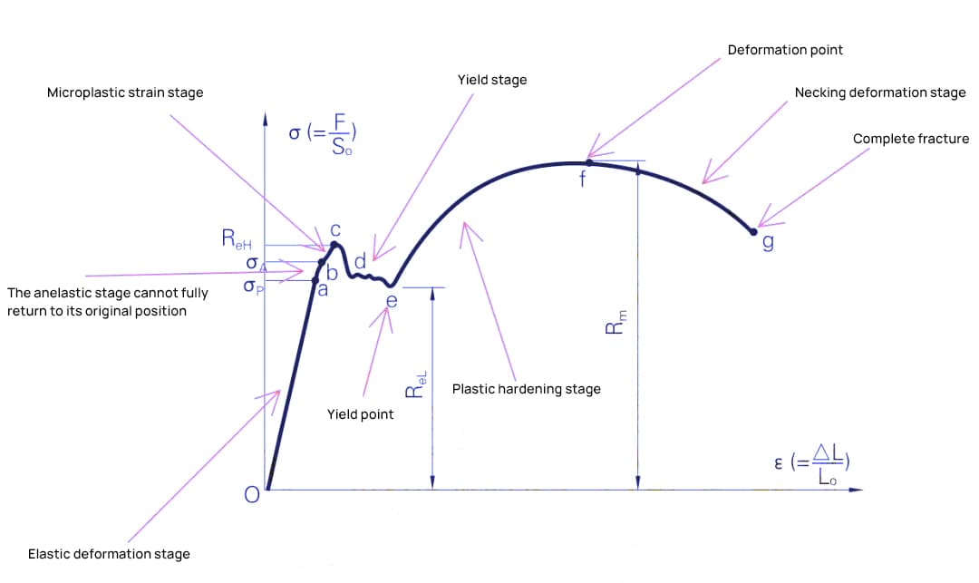
Before discussing the internal radii (R-angles) of workpieces, it is beneficial to understand the characteristics of metallic materials.
As illustrated in the stress-strain curve below, the initial portion represents the elastic deformation phase, where the material can return to its original position after the release of the tensile force.
By continuing to apply force beyond the yield point, the material enters the strain hardening phase, where more tensile force causes permanent plastic deformation. To induce greater plastic deformation, it is necessary to increase the force.
After reaching peak stress, additional tensile force leads to narrowing and eventually complete fracture. During the bending process, deformation of sheet metal occurs mainly in the strain hardening phase, characterized by an increased tension requirement as the deformation increases.
The internal R angle of a part is related to the material, as shown in the graph below.
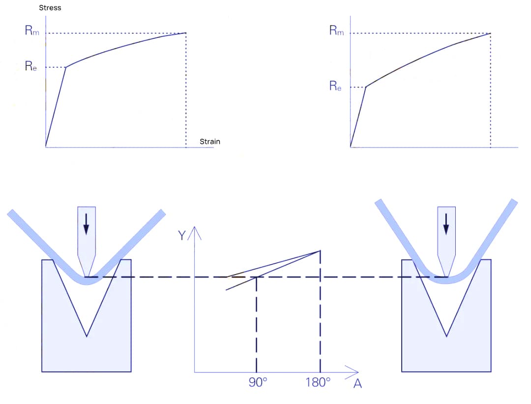
Materials with low strain hardening have smaller internal R angles, while those with high strain hardening have larger internal R angles. The internal R angle is also influenced by the opening of the lower mold die; the smaller the opening, the smaller the internal R angle, as indicated in the Table below.
Table: Relationship between the internal radius of the part and the die opening
| Material | Bending angle | Internal R Angle |
| DC01 (mild steel) | 135° | 0.33V |
| 90° | 0.17V | |
| 45° | 0.12V | |
| AW-5754H22 (aluminum) | 135° | 0.20V |
| 90° | 0.10V | |
| 45° | 0.07V | |
| X5CrNi1810 (stainless steel) | 135° | 0.37V |
| 90° | 0.20V | |
| 45° | 0.17V |
The selection range for the bottom opening of the bending die is normally:
- For sheet metal less than 4 mm thick, a die opening of 6 to 8 times the material thickness;
- For sheet metal over 4mm thick, a die opening of 8 to 12 times the material thickness.
Therefore, the desired internal R angle for a bent part can be achieved by considering material properties in conjunction with the choice of die opening.
Requirements for the upper mold: As long as the R angle of the upper mold does not exceed the standard R angle, it has almost no effect on the internal R angle of the bent part.
- If the required internal angle R of the part is greater than the standard, the radius R of the upper tip of the mold must be increased;
- If the required internal R angle is smaller than the standard, the sheet metal groove or bottom bend can be used, and the radius R of the top tip of the mold must be decreased.
For some materials with low ductility, a larger radius R at the mold tip may also be necessary to bend a larger internal angle R to prevent fracture of the material.
Understanding Sheet Metal Bend Radius
The radius of curvature of sheet metal is an essential aspect to consider when manufacturing or designing parts. It has a significant impact on the quality and functionality of the final product.
In this section, you will learn about bend radius, the factors that influence it, and guidelines for selecting the appropriate minimum bend radius.

Factors that influence the bending radius
The bending radius depends on several factors, such as:
- Material : Different metals have different responses to bending. For example, aluminum can be bent into a tighter radius than steel due to its flexibility.
- Thickness : As the thickness of sheet metal increases, the minimum bending radius also increases.
- Grain direction : Bending along the grain direction requires a larger radius than bending across the grain.
- Bending angle : As the bending angle increases, the bending radius may need to be larger to prevent stress concentration or cracking.
- Tooling : The die and punch used in a press brake also influence the bend radius.
Understanding these factors and their impact on bend radius can help you make informed decisions during the design process and improve the quality and durability of your parts.
Guidelines for Minimum Bend Radius
To avoid the formation of cracks or deformation of the part during bending, it is essential to follow the minimum bend radius guidelines. These guidelines may vary depending on the material and its properties:
- Mild steel : For materials up to 1.2 mm thick, a minimum bending radius of 0.8T is recommended (T = material thickness).
- Aluminum : A minimum bending radius of 2T is normally suggested for materials less than 4mm thick.
- Stainless steel : For thicknesses up to 3 mm, a minimum bending radius of 1.5T is proposed.
These are general guidelines and it is crucial to consult specific material recommendations or experiment with your specific sheet metal and tool combinations to achieve the desired result. By adhering to the appropriate bend radius guidelines, you can ensure a high-quality final product with fewer defects, less waste, and greater strength.