Introduction
The load on sheet metal bending machines is substantial, so the strength of their parts must be high.
Furthermore, with intense competition in the market, reducing the cost of laminated rolls is crucial. This means that the machine must be designed with precision and reliability.
To design the roll calender, it is necessary to first carry out a strength analysis of the rolling mill, which provides the original parameters for designing each part of the machine.
Calculating the motive power of the main drive system is also important for designing the main drive system and selecting the motor.
As a result, calculating the force analysis and driving power of the thick plate rolling mill is critical to the design of the roll calender.
This post provides a method for calculating the force capabilities of a three-roll symmetrical press brake, and other types of sheet metal rolling mills can use it as a reference.
Strength Analysis
2.1 Maximum torque required to roll a cylinder
When the sheet rolling machine is working, the steel sheet must be rolled onto the steel tube.
At this time, the stress of the material has reached the yield point.
Therefore, the distribution of bending stresses in the pipe section is shown below figure (b), and the bending moment M of the section is:
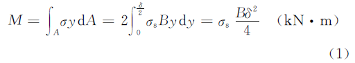
In the above formula,
- B, δ – The maximum width and thickness of the rolled steel sheet (m)
- σ is – Yield limit of the material (kN • i -2 )
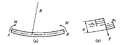
Fig.1 Roll bending stress distribution
When considering the deformation of the material, reinforcement exists, and the reinforcement coefficient K is introduced to modify equation (1), namely:
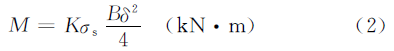
In the above formula,
- K – reinforcement coefficient, the value can be K = 1.10~1.25, when the result for δ/R is large, then take the largest value.
- R – Radius of the neutral layer of the rolling plate (m)
2.2 Force Condition
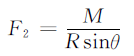
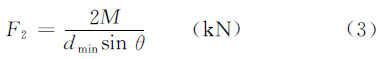
When rolling steel plate, the strength condition is shown as the figure below. According to the balance of forces, the support force F 2 on the roller plate can be obtained using the formula:
In the above formula,
- θ – The angle between the contaminated line OO 1 and OO 2,
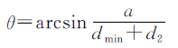
- α – Central distance of the lower roller (m)
- d min – Minimum sheet rolling diameter (m)
- d 2 – Diameter of the lower roll (m)
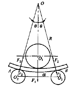
Fig.2 Roll bending force analysis
Considering that the plate thickness δ is much smaller than the minimum diameter of the rolling tube, the radius R of the neutral layer is around 0.5d min to simplify the calculation, the above equation can be changed to:
According to the balance of forces, the pressure force F 1 that is generated by the upper roller, acting on the rolling plate is:

Calculation of driving power
3.1 Lower roller drive moment
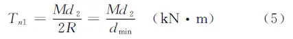
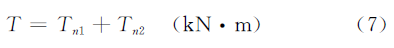
The bottom roll of the plate rolling machine is the driving roll, and the driving torque on the bottom roll is used to overcome the deformation torque T n1 and the friction torque T n2 .
In the steel sheet rolling process, the deformation capacity stored in section AB of the steel sheet (see Fig. 1a and Fig. 2) is 2 M θ the time cost is 2 θR/V ( V is the rolling speed ).
The relationship is equal to the power of the deformation torque T n1 , namely:
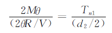
Therefore,
The friction torque includes the rolling friction torque between the upper and lower roller and the steel plate, and the sliding friction torque between the roller neck and the shaft sleeve, which can be calculated as follows:
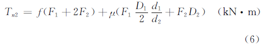
In the formula above:
- f – Rolling friction coefficient, take f = 0.008m
- μ – Sliding friction coefficient, take μ = 0.05-0.1d 1 ,
- d 2 – Diameter of the upper roller and lower roller (m)
- D 1 D 2 – Upper and lower roll neck diameter (m)
The size is not yet precise at the design stage, the value may take D i = 0.5d i (i = 1, 2). The lower roller drive torque T is equal to the sum of the deformation torque T n1 and the friction torque T n2 .
3.2 Power driven by the lower roller
The power driven by the lower roller is:
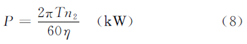
In the formula above:
- P – Power activated (m • KW)
- T – Moment of driving force (KN • m)
- n 2 – Lowest roller rotation speed (r • min -1 ), n 2 =2 V /d 2 (V is the rolling speed)
- η – transmission efficiency, η=0.65-0.8
The power of the main engine can be obtained from the value of P.