The degree of deformation in flanging or flanging operations is commonly represented by the flanging coefficient, which is calculated using the following formula:
In the formula:
- Ko flanging coefficient;
- D 0 – the diameter of the pre-drilled hole in millimeters (mm);
- d – average diameter of the ruler after flanging (mm).
The higher the K value, the smaller the deformation; conversely, the lower the value of K, the greater the deformation.
The main factors that affect the flanging coefficient are as follows:
1. The properties of the material; the better the plasticity, the lower the K value can be.
2. The relative diameter of the pre-drilled hole, t/D 0 ; the smaller the t/D 0 value, the higher the K value.
3. The hole processing method; Drilled holes, due to the absence of a tear surface, are less likely to crack during flanging. Drilled holes, having some torn surfaces, are prone to cracking, thus requiring a higher K value. If the material is annealed after punching or if the hole is finished, a flanging relationship close to that of drilled holes can be achieved.
Additionally, reversing the direction of the punch in relation to the direction of the flange, with the burrs located on the inside of the flange, can reduce cracking, as shown in Figure 5-4.
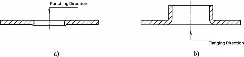
a) Drilling b) Flanging
4. When using a spherical, parabolic or conical punch for drilling, the edges of the hole are widened smoothly and gradually, reducing the K factor and increasing the degree of deformation. The limiting piercing coefficient for low-carbon steel is shown in Table 5-1, and the piercing coefficients for various materials are listed in Table 5-2.
5-1 The final piercing coefficient for low carbon steel.
| Pilot Punch Profile | Hole machining methods | Relative material thickness, d 0 / t | ||||||||||
| 100 | 50 | 35 | 20 | 15 | 10 | 8 | 6. 5 | 5 | 3 | 1 | ||
| Ball punch | Deburring after drilling. | 0.70 | 0.60 | 0.52 | 0.45 | 0.40 | 0.36 | 0.33 | 0.31 | 0:30 | 0.25 | 0.20 |
| Drill holes with a drilling die. | 0.75 | 0.65 | 0.57 | 0.52 | 0.48 | 0.45 | 0.44 | 0.43 | 0.42 | 0.42 | – | |
| Cylindrical Punch | Deburring after drilling. | 0.80 | 0.70 | 0.60 | 0.50 | 0.45 | 0.42 | 0.40 | 0.37 | 0.35 | 0.3 | 0.25 |
| Drill holes with a drilling die. | 0.85 | 0.75 | 0.65 | 0.60 | 0.55 | 0.52 | 0.50 | 0.50 | 0.48 | 0.47 | – | |
5-2 Flanging Rates of Various Materials
| Annealed raw material | Hole Flange Ratio | ||
| K0 | kmmin | ||
| Galvanized steel sheet (white iron) | 0.70 | 0.65 | |
| Mild steel | t = 0.25 ~ 2.0mm | 0. 72 | 0. 68 |
| t =3. 0 ~ 6.0mm | 0.78 | 0.75 | |
| H62 brass, thickness ranging from 0.5 to 6.0 mm | 0. 68 | 0. 62 | |
| Aluminum, thickness ranging from 0.5 to 5.0 mm | 0.7 | 0. 64 | |
| Hard aluminum alloy | 0. 89 | 0. 80 | |
| titanium alloy | TA1 (cold state) | 0.64 ~ 0.68 | 0.55 |
| TA1 (heated to 300-400°C) | 0.40 ~ 0.50 | – | |
| TA5 (cold state) | 0.85 ~ 0.90 | 0.75 | |
| TA5 (heated to 500-600°C) | 0.70 ~ 0.65 | 0.55 | |
| Stainless steel, high temperature alloys | 0.69 ~ 0.65 | 0.61 ~ 0.57 | |