
Detailed classification of adjustments used in engineering metrology
INTRODUCTION
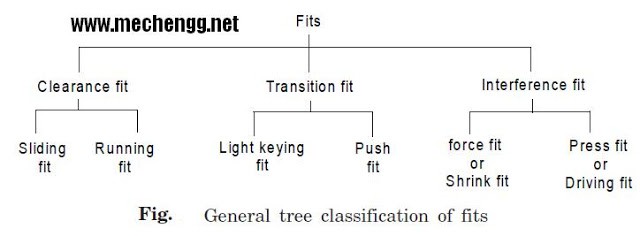
FITS AND THEIR CLASSIFICATIONS
When two parts need to be assembled, the relationship resulting from the difference between their sizes before assembly is called fit. A fit can be defined as the degree of tightness and looseness between two mating parts.
Adjustments depend on the actual limits of the hole and/or shaft and can be divided into three general classes:
(i) Slack adjustment.
(ii) Interference adjustment.
(iii) Transition Adjustment.
Slack adjustment
In loose fit, there is an air space or gap between the shaft and the hole, as shown in Figure . These adjustments provide a loose joint. A loose fit has positive allowance, that is, there is a minimum positive gap between the upper limit of the shaft and the lower limit of the hole.
 Settlement Fit – Loose Fit, Running Fit, Slip Fit
Backlash adjustment can be subclassified as follows:
Loose fit
It is used between mating parts where no precision is required. It provides minimum allowance and is used in loose pulleys, agricultural machinery etc.
Running in shape
For a racing fit, the shaft dimension must be smaller enough to maintain a film of oil for lubrication. It is used in pair of bearings, etc. A tolerance of 0.025mm per 25mm rim diameter can be used.
Slide adjustment or medium adjustment
It is used in the coupling parts where great precision is required. It provides medium tolerance and is used in tool slides, valve slides, auto parts, etc. .
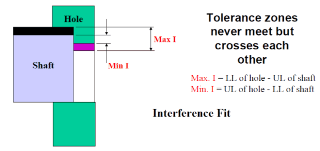
Interference fitting
A negative difference between the diameter of the hole and the shaft is called interference. In such cases, the shaft diameter is always larger than the hole diameter. In the Figure, the interference fit has a negative tolerance, that is, the interference exists between the upper limit of the hole and the lower limit of the shaft.
In this adjustment, the hole tolerance zone is always below that of the shaft. The shaft is assembled by pressure or thermal expansion.
 Interference fit – retractable fit, medium force fit, tight fit
Contraction adjustment or heavy force adjustment
Interference tuning can be subclassified as follows:
Refers to the maximum negative subsidy. In hole and shaft assembly, the hole is expanded by heating and then quickly cooled into position. It is used in assembling rims etc.
Medium strength adjustment
These fits have medium negative tolerance. Considerable pressure is required to assemble the bore and shaft. It is used in car wheels, dynamo armature etc.
Tight fit or pressure fit
One part can be assembled into the other with a hand hammer or light pressure. There is a slight negative margin between two mating parts (more than a twist fit). It offers semi-permanent adjustment and is used on keyed pulleys and shafts, rocker arms, etc.
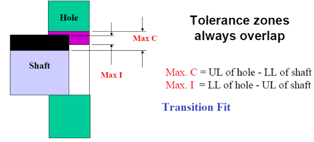
Transition adjustment
This may result in clearance fit or interference fit, depending on the actual value of the individual tolerances of the corresponding components. Transition fits are a compromise between backlash and interference fits. They are used for applications where precise location is important but slight play or interference is allowable. As shown in Figure, there are overlapping hole and shaft tolerance zones.
Transition adjustment can be subclassified as follows:
 Transition adjustment – pressure adjustment, force adjustment, twist adjustment
Pressure adjustment
It refers to zero tolerance and light pressure (10 cating pins, pins, etc.) is required when assembling the hole and shaft. Moving parts show less vibration with this type of adjustment. It is also known as a snug fit.
Force fit or shrink
A force fit is used when the two coupling parts must be rigidly fixed so that one cannot move without the other. It requires high pressure to force the shaft into the hole or the hole to be expanded by heating. It is used in railway wheels, etc.
Twist adjustment
There is a slight negative tolerance between two coupling parts in torsion adjustment. It requires pressure to force the shaft into the hole and provides a lightweight assembly. It is used to fix keys, pins, etc.


