
Hydraulic oil, when compressed in a hydraulic cylinder, generates significant pressure. This pressure is used in several mechanical devices and today we will discuss the specifics of hydraulic cylinders.
A hydraulic cylinder is a hydraulic actuator that transforms hydraulic energy into mechanical energy, performing linear reciprocating movements (or oscillating movements). Its structure is simple and its operation is reliable.
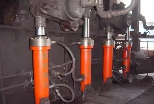
When it is used to perform reciprocating movements, it can eliminate the need for deceleration devices, and there is no transmission backlash, ensuring smooth movement. Therefore, it is widely used in various machine hydraulic systems.
The output force of a hydraulic cylinder is directly proportional to the effective area of the piston and the pressure difference on both sides of it. A hydraulic cylinder essentially consists of a cylinder and cylinder head, piston and piston rod, sealing device, damping device and exhaust device.
Buffer and exhaust devices depend on the specific application, while the other devices are indispensable.
I. Composition of the Hydraulic Cylinder
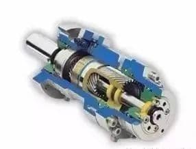
A hydraulic cylinder typically consists of a rear end cap, cylinder, piston rod, piston assembly, front end cap and other major components.
To prevent oil leakage from the hydraulic cylinder or leakage from the high pressure chamber to the low pressure chamber, sealing devices are installed between the cylinder and the end cap, the piston and the piston rod, the piston and the cylinder, and the piston rod and front end cap.
On the outside of the front cover, a dust protection device is also installed. To prevent the piston from hitting the cylinder cover when quickly returning to the end of the stroke, a damping device is installed at the end of the hydraulic cylinder, and sometimes an exhaust device is also required.
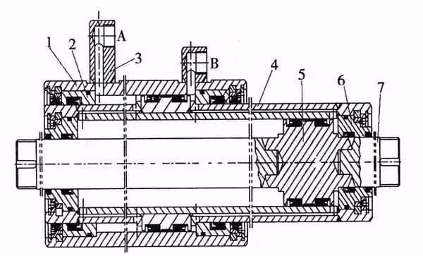
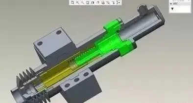
1- Cylinder Drum;
2- External Cylinder Guide Sleeve;
3- Branch tube;
4- Rod Cylinder Set;
5- Piston;
6- Internal Cylinder Guide Body;
7- Piston rod.
Cylinder:
The cylinder is the main part of the hydraulic cylinder. It forms a closed chamber with the cylinder cover and other parts to move the piston.
Cylinder cover:
The cylinder cover is installed at both ends of the hydraulic cylinder, forming a tight oil chamber with the cylinder. Connection methods typically include welding, threads, screws, wrenches, and tie rods. The choice depends on factors such as working pressure, cylinder connection method and operating environment.
Piston rod:
The piston rod is the main element of the hydraulic cylinder for transmitting force. The material is generally medium carbon steel (such as 45# steel). The piston rod is subject to thrust, tension, or bending moment during cylinder operation. Its resistance must be guaranteed and its fit in the guide sleeve, where it frequently slides, must be adequate.
Piston:
The piston is the main element for converting hydraulic energy into mechanical energy. Its effective working area directly affects the force and movement speed of the hydraulic cylinder. There are several forms of connection between the piston and the piston rod, including snap ring type, bushing type and nut type.
Guide sleeve:
The guide sleeve guides and supports the piston rod. It requires high precision, low friction resistance, good wear resistance and the ability to withstand the pressure, bending force and impact vibration of the piston rod.
It is equipped with a sealing device to ensure the sealing of the rod chamber and a dust ring on the outside to prevent impurities, dust and moisture from damaging the seal.
Buffer device:
When the piston and piston rod move under hydraulic pressure, they have significant thrust. When they hit the cover and bottom of the cylinder, they can cause mechanical collision, resulting in high impact pressure and noise. The buffer device is used to avoid this collision.
Its working principle is to convert the kinetic energy of the hydraulic oil in the low pressure chamber of the cylinder (full or partial) into thermal energy through throttling. Thermal energy is then transported from the hydraulic cylinder by the circulating oil.
The buffer device is divided into two types: constant throttling area buffer device and variable throttling buffer device.
II. Hydraulic Transmission Principles
Hydraulic transmission uses oil as its working medium, transmitting movement through changes in sealed volume and power through internal pressure within the oil.
Power component: Transforms the mechanical energy of the main engine into hydraulic energy (pressure energy), for example the hydraulic pump.
Actuation component: Converts the pump's hydraulic energy input into mechanical energy, activating the working mechanism. Examples include hydraulic cylinders and motors.
Control component: Regulates and controls oil pressure, flow and direction. Examples include pressure control valves, flow control valves, and direction control valves.
Auxiliary Component: Connects the above three components into one system, serving functions such as oil storage, filtration, metering and sealing. Examples include piping and connectors, oil tanks, filters, accumulators, seals, and control instruments.
III. Classification of Hydraulic Cylinders by Structure
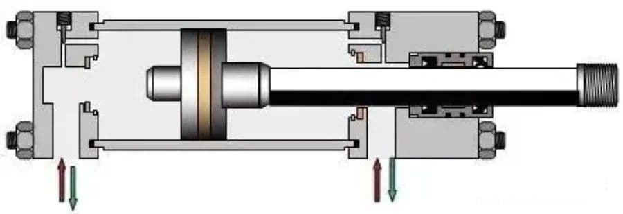
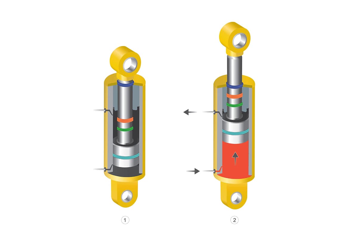
Piston type Hydraulic Cylinder:
A single-rod hydraulic cylinder has a rod at only one end. Both oil inlet and outlet ports A and B can transmit pressurized oil or return oil, allowing bidirectional movement, which is why it is called a double-acting cylinder.
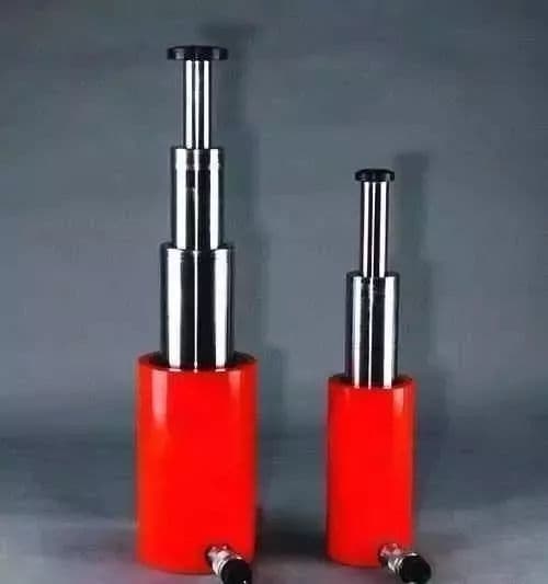
Telescopic Hydraulic Cylinder:
Features a two- or multi-stage piston. In a telescopic hydraulic cylinder, the piston extension sequence is from largest to smallest, while the unloaded retraction sequence is generally from smallest to largest.
Telescopic cylinders can achieve longer strokes, but their retracted length is shorter, making the structure compact. This type of hydraulic cylinder is commonly used in construction and agricultural machinery.
Balance Hydraulic Cylinder:
A component performing output torque and reciprocating motion, also known as a swing hydraulic motor. Available in single reed and double reed variants. The stator block is fixed to the cylinder body, while the vane and rotor are connected. Depending on the direction of oil flow, the vane will cause the rotor to rock back and forth.
4. Main Parameters of Hydraulic Cylinders
The main parameters of hydraulic cylinders include pressure, flow, size specification, piston stroke, movement speed, push-pull force, hydraulic cylinder efficiency and power, among others.
Pressure:
Pressure is the intensity of the force exerted by the oil on a unit area. The calculation formula is p=F/A, where F is the load acting on the piston divided by the effective working area of the piston. In the same effective working area of a piston, the greater the load, the greater the pressure required to overcome the load.
Based on working pressure, hydraulic cylinders can be classified into low pressure hydraulic cylinders (70kgf/cm² or 7Mpa), medium pressure (140kgf/cm² or 14Mpa) or high pressure (210kgf/cm² or 21Mpa).
| Rated Pressure Series of Hydraulic Cylinders | ||||||||||
| 0.63 | 1.0 | 1.6 | 2.5 | 4.0 | 6.3 | 10.0 | 16.0 | 25.0 | 31.5 | 40.0 |
| Hydraulic cylinder piston stroke series | ||||||||||
| First grade | 25 | 50 | 80 | 100 | 125 | 160 | 200 | 250 | 320 | 400 |
| 500 | 630 | 800 | 1000 | 1250 | 1600 | 2000 | 2500 | 3200 | 4000 | |
| Second Serie | 40 | 63 | 90 | 110 | 140 | 180 | ||||
| 220 | 280 | 36 | 450 | 550 | 700 | 900 | 1100 | 1400 | 1800 | |
| 2900 | 2800 | 3600 | ||||||||
| Third grade | 240 | 260 | 300 | 340 | 380 | 420 | 480 | 530 | 600 | 650 |
| 750 | 850 | 950 | 1050 | 1200 | 1300 | 1500 | 1700 | 1900 | 2100 | |
| 2400 | 2600 | 3,000 | 3400 | 3800 | ||||||
| Hydraulic Cylinder Bore Size Series | |||
| 8 | 40 | 125 | (280) |
| 10 | 50 | (140) | 320 |
| 12 | 63 | 160 | (360) |
| 16 | 80 | (180) | 400 |
| 20 | (90) | 200 | (450) |
| 25 | 100 | (220) | 500 |
| 32 | (110) | 250 | |
| Hydraulic Cylinder Piston Rod Outer Diameter Size Series | ||||
| 4 | 18 | 45 | 110 | 280 |
| 5 | 20 | 50 | 125 | 320 |
| 6 | 22 | 56 | 140 | 360 |
| 8 | 25 | 63 | 160 | |
| 10 | 28 | 70 | 180 | |
| 12 | 32 | 80 | 200 | |
| 14 | 36 | 90 | 220 | |
| 16 | 40 | 100 | 250 | |
Flow:
Flow is the volume of oil that passes through the effective cross-sectional area of the cylinder per unit time. The calculation formula is Q=V/t=vA, where V is the volume of oil consumed in one stroke of the hydraulic cylinder piston, t is the time required for one stroke of the hydraulic cylinder piston, v is the piston speed rod and A is the effective working area of the piston.
Piston stroke:
Piston stroke refers to the distance traveled by the piston in its reciprocating movement between two extremes. Generally, after the cylinder stability requirement is met, a standard stroke close to the actual working stroke is selected.
Piston speed:
The speed of movement is the distance that the pressurized oil pushes the piston per unit of time, represented as v=Q/A.
Size Specifications:
Size specifications mainly include cylinder inner and outer diameters, piston diameter, piston rod diameter and cylinder head dimensions. These dimensions are calculated, designed and verified based on the hydraulic cylinder operating environment, installation method, required push-pull force and stroke.
V. Internal Design of the Hydraulic Cylinder
Project Objective: Determined based on on-site operating temperature, working environment, and manufacturing conditions in our factory. Internal structure dimensions are calculated based on the Mechanical Design Handbook.
- Seal selection should be based on the operating temperature at the site, environmental pollution conditions and the working environment. Polyurethane seals cannot be used with water-ethylene glycol media.
- The hydraulic cylinder head should ideally use a V-type combined seal to compensate for errors in the smoothness of groove processing.
- The dimensions of the sealing grooves must strictly comply with the design manual.
- Generally, hydraulic cylinder piston seals use Glyd rings together with guide tapes, as Glyd rings have good high temperature resistance and anti-pollution properties.
- Typically, air cylinder seals use Japanese NOK series. Domestic hydraulic cylinder seals should not be used as they cause too much resistance to cylinder starting, leading to unstable operation or even failure.
- The sealing ring between the hydraulic cylinder head, cylinder bottom and cylinder body should ideally have a locking ring to compensate for manufacturing errors.
- The connection between the cylinder body, cylinder head, cylinder bottom and intermediate swing must avoid welding, as it may cause deformation of the cylinder body. Chained connections or other methods can be used.
SAW. Common Hydraulic Cylinder Problems and Maintenance
Oil leak in the hydraulic cylinder:
External leakage refers to the leakage of oil from various unsealed parts into the atmosphere outside the hydraulic cylinder. The most common external leaks occur in the following three locations:
(1) Oil leakage from the seal between the hydraulic cylinder sleeve and the cylinder cover (or guide sleeve) (Solution: Replace with a new O-ring).
(2) Oil leakage due to relative movement between the piston rod and guide sleeve (Solution: If the piston rod is damaged, clean it with gasoline, dry it, apply metal adhesive to the damaged area, and then , move the piston rod oil seal back and forth on the piston rod to scrape off excess adhesive.
Once the adhesive has fully cured, it can be put back into use. If the guide bushing is worn, a slightly smaller diameter guide bushing can be machined for replacement).
(3) Oil leakage caused by poor sealing of the hydraulic cylinder tube joint (Solution: In addition to checking the sealing condition of the seal ring, check whether the gasket is assembled correctly, whether it is screwed tightly and whether the contact surface has any scratches, etc. If necessary, replace or repair).
Hydraulic cylinder internal leakage refers to the oil in the hydraulic cylinder internally leaking from the high pressure chamber to the low pressure chamber through various gaps.
Internal leakage is more difficult to detect and can only be judged by system operating conditions such as insufficient thrust, speed decline, unstable operation, or increased oil temperature. Hydraulic cylinder internal leakage usually occurs in the following two locations:
(1) The static sealing part between the piston rod and the piston (Solution: Install an O-ring on the sealing surface between them).
(2) The dynamic sealing part between the inner wall of the cylinder liner and the piston (Solution: When an internal leak is detected, a strict inspection of each mating part must be carried out. Cylinder liner repair generally involves drilling of the internal hole, followed by the assembly of a larger diameter piston).


1comment
Sobre cilindros