Brake master cylinders:
In automotive engineering, the master cylinder is a control device that converts non-hydraulic pressure (usually from the driver's foot) into hydraulic pressure. This device controls the slave cylinders located at the other end of the hydraulic system.
As the piston(s) move along the bore of the master cylinder, this movement is transferred through the hydraulic fluid, resulting in movement of the slave cylinder(s). The hydraulic pressure created by the movement of a piston (within the master cylinder bore) toward the slave cylinder(s) compresses the fluid uniformly, but varying the comparative surface area of the master cylinder and/or each slave cylinder, the amount of force and displacement applied to each slave cylinder can be varied in relation to the amount of force and displacement applied to the master cylinder.
Function of brake master cylinders:
The brake master cylinder (BMC) is nothing more than a highly advanced piston and cylinder assembly.
The purpose of the BMC is to build hydraulic pressure and works based on the basic principle of Pascal's Law
So how a BMC creates hydraulic pressure, it does so using some complicated piston, seals, and spring configurations.
Master cylinder diagram:
The operating principle is that of Pascal's Law where a high pressure fluid is obtained at the smaller area exit of a cylinder by applying force to the larger area entrance area.
 hydraulic master cylinders
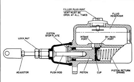
The image below is a cut section of a BMC. The main parts that we will deal with and that are sufficient to understand the function of the BMC are
1) Reservoir – which contains the brake fluid
2) Primary and Secondary Piston – which acts as a piston
3) Seals – seals the door and also seals the chambers.
The master cylinder can rightly be termed as the heart of the hydraulic brake system. There are two main chambers, viz. the fluid reservoir and the compression chamber in which the piston operates (Fig. The fluid in the reservoir compensates for any change in the volume of fluid in the pipes due to temperature variations and, to some extent, due to leaks. To prevent leaks, there are rubber seals at both ends of the piston in the compression chamber The reduced diameter region of the piston is always surrounded by the fluid A rubber boot covers the rod end of the master cylinder to prevent dirt from entering the brake line side. . compression chamber, there is a fluid check value with a rubber cup inside. It serves to retain residual pressure in the brake lines even when the brakes are released.
Operation of Master Cylinders:
When the brake pedal is pressed, the pressure rod moves to the left moving the piston against the force of the spring as it covers the bypass port, a pressure builds up in the compression chamber When enough pressure is built up, the check valve of fluid bypasses and fluid under pressure flows in the piping. When the brake pedal is released, spring force in the master cylinder moves the piston to the right. This same spring force keeps the check valve pressed in its seat for some time, delaying the return of fluid to the compression chamber. This delay causes a vacuum in the compression chamber and there may be a chance of air leaking into the system. This vacuum is destroyed by fluid entering the reservoir through the intake port and holes in the piston that bypass the rubber cup and enter the compression chamber.