-
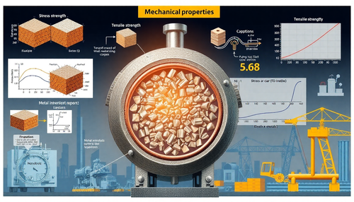
Propriedades Mecânicas dos Metais: Entendendo a Resistência e Durabilidade
Frequentemente, os materiais estão sujeitos a uma força externa quando são usados. Engenheiros mecânicos calculam essas forças, e cientistas de materiais determinam como os materiais se deformam ou...
-
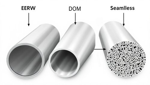
Entendendo os diferentes tipos de Tubos de Aço: ERW, DOM e Sem Costura
Este mês, examinamos as diferenças entre ERW, DOM e tubos sem costura. Tubos ERW (Electric Resistance Welded) ERW se refere a um processo de soldagem que envolve soldagem por pontos e por costura, ...
-

Como verificar a dureza do metal sem uma máquina Rockwell
Por muito tempo, pensei que a única maneira de verificar corretamente a dureza do metal era com uma máquina de teste Rockwell adequada. Felizmente, aprendi algumas outras técnicas simples e eficaze...
-
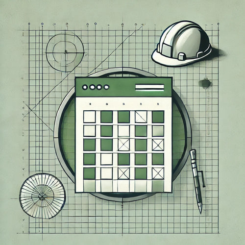
Curso com Planilhas Automáticas para Engenharia Civil
Planilhas Automáticas para Engenharia Civil: Cálculo e Dimensionamento Simplificados
Na engenharia civil, precisão e eficiência são vitais para o sucesso de qualquer projeto. No entanto, o process...
-
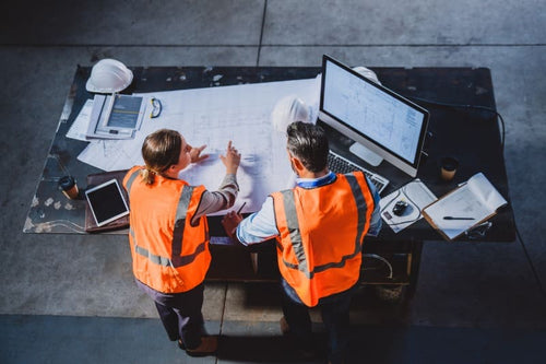
Curso de Power BI para Engenharia Civil
Power BI na Engenharia Civil: Da Introdução às Aplicações Avançadas
No cenário competitivo da engenharia civil e da construção, a capacidade de gerenciar e analisar dados se tornou uma habilidade ...
-

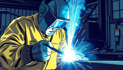
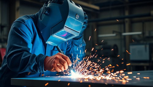
Cursos de Soldagem: Programa Completo para Iniciantes e Profissionais
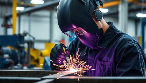
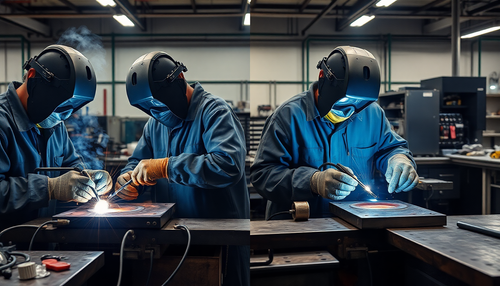
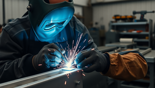
Qualificação Profissional em Soldagem: Cursos Estratégicos para Atuar com Sucesso na Indústria
A soldagem é uma das habilidades mais críticas e requisitadas na indústria, especialmente em setores...
-
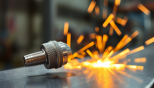
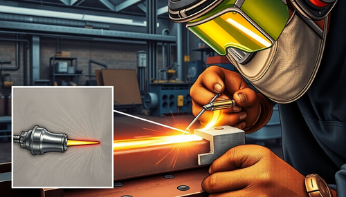
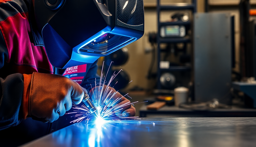
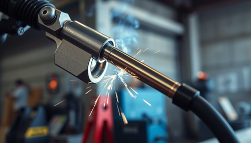
Como prolongar a Vida Útil do Bico de Contato na Solda MIG
A solda MIG (Metal Inert Gas) é uma técnica amplamente utilizada na indústria e construção devido à sua eficiência, versatilidade e qualidade dos resultados. No entanto, um componente crucial neste...
-
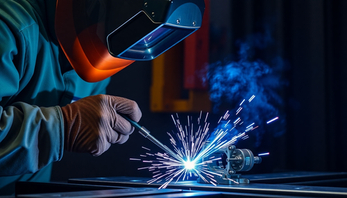
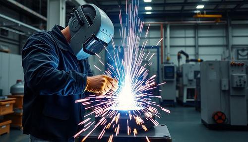
Como manter o Arco Elétrico Estável durante a Soldagem
A soldagem é uma técnica essencial em diversas indústrias, desde a construção civil até a fabricação de automóveis. No entanto, um dos desafios mais comuns enfrentados pelos soldadores é a manutenç...
-

Como Eliminar Respingos Excessivos na Soldagem MIG
A soldagem MIG (Metal Inert Gas) é uma técnica amplamente utilizada na indústria e construção, conhecida por sua eficiência e versatilidade. No entanto, um dos desafios comuns enfrentados pelos pro...
-
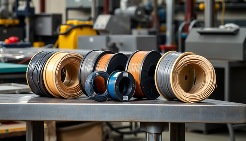
Como escolher o arame correto para solda MIG
A escolha do arame correto para solda MIG é fundamental para obter resultados de alta qualidade e eficiência no processo de soldagem. Cada tipo de arame possui características específicas que afeta...
-
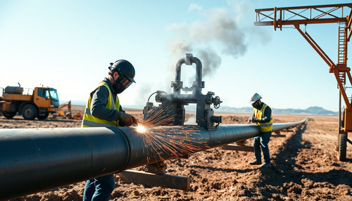
Soldagem de Tubulações em Campo: Preparação e Sequenciamento
A soldagem de tubulações em campo é um desafio único que requer habilidades especializadas e planejamento cuidadoso. Diferente da soldagem em ambiente controlado de oficina, a soldagem em campo enf...
-
Soldagem em Peças Pintadas: Evitando Problemas e Garantindo Segurança
A soldagem é uma técnica fundamental em diversos setores industriais, desde a fabricação de automóveis até a construção civil. No entanto, quando se trata de soldar peças que já foram pintadas, é e...
-
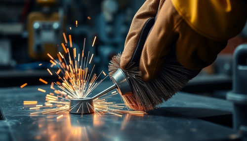
Escovas de Aço na Soldagem: Preparação e Acabamento Perfeitos
A soldagem é uma técnica fundamental em diversas indústrias, desde a construção civil até a fabricação de maquinário pesado. No entanto, para obter resultados de alta qualidade, é essencial prepara...
-
Entendendo o Processo de Brasagem: Quando e Como Utilizá-lo
A brasagem é uma técnica de união de metais que se diferencia da solda tradicional por fusão. Enquanto a solda envolve o derretimento e a mistura dos metais, a brasagem utiliza uma liga de metal de...
-
Importância da Limpeza Pós-Soldagem em Aço Inox e Alumínio
A soldagem é uma técnica fundamental em diversos setores industriais, desde a construção civil até a fabricação de equipamentos. No entanto, após o processo de soldagem, é essencial realizar uma li...
-
Identificando e Corrigindo a Falta de Penetração na Solda
A integridade estrutural de uma junta soldada depende crucialmente da qualidade da penetração da solda. Quando a penetração é insuficiente, a resistência da união fica comprometida, podendo levar a...
-
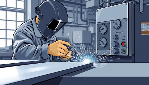
Processo de Soldagem por Resistência Elétrica: Entendendo os Detalhes Técnicos
A soldagem por resistência elétrica, também conhecida como solda por ponto ou spot weld, é uma técnica amplamente utilizada na indústria, especialmente na fabricação de automóveis e estruturas metá...
-

Soldagem em Aço Inoxidável: Evitando os Erros Mais Comuns
A soldagem de aço inoxidável é uma tarefa delicada que requer atenção aos mínimos detalhes. Diferente da soldagem de aços carbono, o processo de união de peças em aço inoxidável envolve desafios es...
-

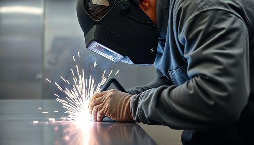
Importância do Controle da Velocidade de Avanço na Soldagem
A soldagem é uma técnica fundamental em diversas indústrias, desde a construção civil até a fabricação de automóveis. No entanto, para obter resultados de alta qualidade, é essencial dominar divers...
-
Soldagem de Titânio: Superando Desafios e Impulsionando a Inovação
O titânio é um material fascinante, conhecido por sua resistência, leveza e biocompatibilidade. No entanto, a soldagem desse metal nobre apresenta desafios únicos que exigem técnicas especializadas...
-
Como usar gabaritos e fixações para garantir soldagens precisas
A precisão é fundamental quando se trata de soldagem. Peças mal alinhadas ou deslocadas podem resultar em juntas defeituosas, reduzindo a integridade estrutural e a aparência final do trabalho. Fel...
-

Técnicas Essenciais de Ponteamento para Montagem de Estruturas Metálicas
A montagem de estruturas metálicas é uma etapa crucial no processo de construção, exigindo técnicas precisas e cuidadosas para garantir a estabilidade e o alinhamento adequado das peças. Uma das té...
-
Poça de Fusão: Técnicas Essenciais para Soldagem TIG Perfeita
A soldagem TIG (Tungsten Inert Gas) é uma técnica versátil e precisa, amplamente utilizada na indústria e construção. No entanto, manter a poça de fusão sob controle pode ser um desafio, especialme...
-
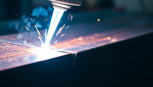
Soldagem a Plasma: Tecnologia para a Indústria e Construção
A soldagem a plasma, também conhecida como PAW (Plasma Arc Welding), é uma técnica de soldagem avançada que vem revolucionando a indústria e a construção. Essa tecnologia oferece uma solução eficie...
-
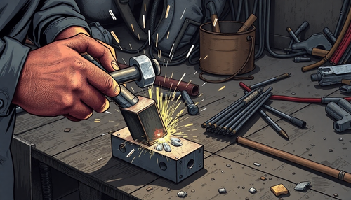
Importância do Martelo de Escória na Soldagem com Eletrodo Revestido
A soldagem com eletrodo revestido é uma técnica amplamente utilizada na indústria e construção civil, sendo essencial para a união de metais e a fabricação de estruturas robustas. No entanto, o pro...
-
Como fazer uma Solda Filetada com Qualidade Profissional
A solda filetada, também conhecida como solda em ângulo, é uma técnica amplamente utilizada na indústria e na construção civil para unir peças metálicas em ângulo. Essa técnica é essencial para a f...
-
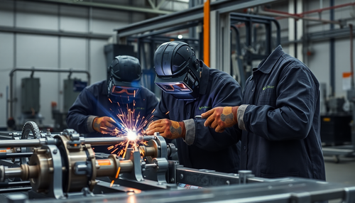
Entendendo os Tipos de Soldagem: Manual, Semiautomática e Automática
A soldagem é uma técnica fundamental em diversos setores industriais, desde a fabricação de automóveis até a construção civil. No entanto, nem todas as técnicas de soldagem são iguais. Existem três...
-

Entendendo a Escorificação na Soldagem: Causas, Impactos e Soluções
A soldagem é uma técnica fundamental em diversos setores industriais, desde a construção civil até a fabricação de máquinas e equipamentos. No entanto, durante o processo de soldagem, um fenômeno i...
-

Diferença entre solda TIG DC e TIG AC: quando usar cada uma
A solda TIG (Tungsten Inert Gas) é uma técnica amplamente utilizada na indústria e construção, conhecida por sua precisão, qualidade e versatilidade. No entanto, existem duas variantes principais d...
-
Soldagem em Aço Carbono Espesso: Desafios e Soluções
A soldagem de aço carbono espesso é um desafio constante para profissionais da indústria e construção. Essas peças exigem cuidados especiais durante o processo de soldagem, a fim de garantir a inte...
-

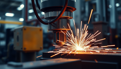
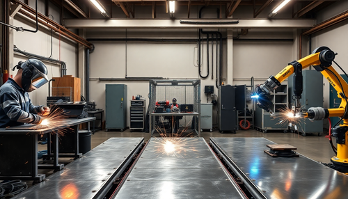
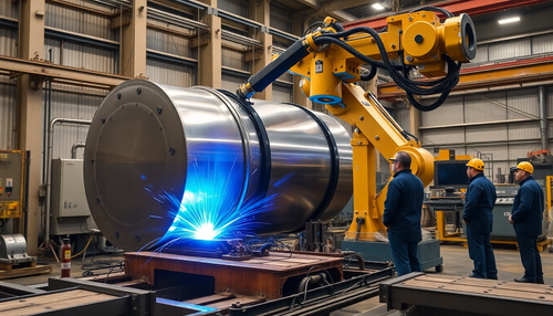
Como a Soldagem Robotizada Transforma a Indústria
A evolução tecnológica tem impulsionado transformações significativas em diversos setores industriais, e a soldagem robotizada é um exemplo claro dessa realidade. Essa técnica avançada vem se conso...
-
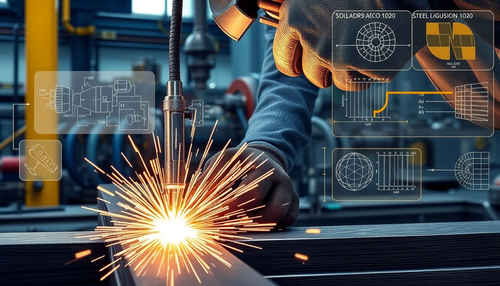
Soldar Aço 1020 corretamente: Evite trincas e Garanta Qualidade
O aço SAE AISI 1020 é um dos materiais mais utilizados na indústria e construção civil devido à sua versatilidade e custo-benefício. Esse aço carbono de baixa liga é amplamente empregado em estrutu...
-
Como Soldar Aço Inox com TIG Sem Contaminação: Um Guia Passo a Passo
A soldagem de aço inoxidável é uma tarefa delicada que requer atenção especial para evitar contaminação e obter um acabamento limpo e profissional. A técnica de soldagem TIG (Tungsten Inert Gas) é ...
-
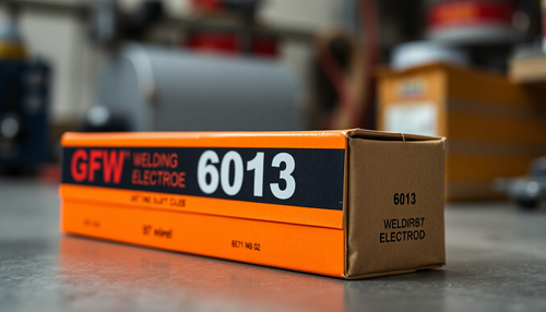
Como identificar e utilizar o Eletrodo 6013
O eletrodo 6013 é um dos tipos mais comuns e versáteis de eletrodos de soldagem utilizados na indústria e construção civil. Sua popularidade se deve às suas características únicas, que o tornam ide...
-
Como fazer uma Solda no Eletrodo Revestido
A solda com eletrodo revestido é uma técnica amplamente utilizada na indústria e construção civil devido à sua versatilidade e facilidade de aplicação. Neste artigo, vamos explorar detalhadamente o...
-
Garantia de Qualidade em Soldas: Os Principais Testes Não Destrutivos
A integridade e a qualidade das soldas são fundamentais em diversos setores industriais, desde a construção civil até a fabricação de equipamentos de alta tecnologia. Para assegurar que as juntas s...
-
Como ajustar Corretamente a Amperagem na Solda com Eletrodo Revestido
A solda com eletrodo revestido é uma técnica amplamente utilizada na indústria e construção, sendo essencial para a união de peças metálicas. Um dos fatores críticos neste processo é o ajuste preci...
-

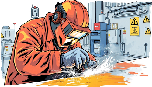
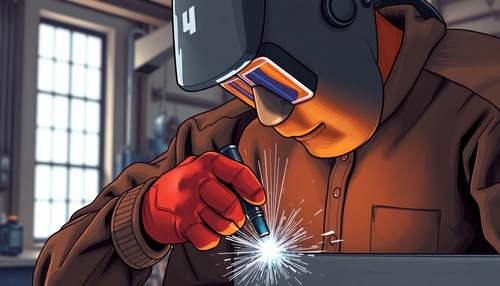
Equipamentos de Proteção Individual (EPIs) obrigatórios para Soldadores
A segurança é um fator primordial no ambiente de trabalho, especialmente para profissionais que lidam com atividades de alto risco, como a soldagem. Os Equipamentos de Proteção Individual (EPIs) sã...
-
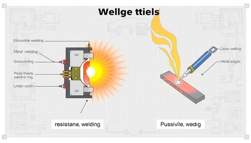
Diferença entre Solda por Resistência e Solda por Fusão: Aplicações Práticas
A escolha do processo de soldagem correto é crucial para garantir a integridade e a eficiência de diversas aplicações industriais, desde a fabricação de automóveis até a construção de aeronaves. Ne...
-

A Soldagem Orbital: Precisão e Eficiência
A soldagem orbital é uma técnica revolucionária que está transformando a maneira como as indústrias abordam a união de materiais. Essa abordagem automatizada e precisa tem se destacado em diversos ...
-
Como Regular sua Inversora MIG para Chapas Finas
A solda MIG (Metal Inert Gas) é uma técnica amplamente utilizada na indústria e construção, conhecida por sua versatilidade e eficiência. No entanto, quando se trata de trabalhar com chapas finas, ...
-
5 Erros Comuns na Soldagem com Alumínio
A soldagem de alumínio é uma técnica desafiadora que requer atenção aos detalhes e conhecimento especializado. Infelizmente, muitos profissionais cometem erros comuns que podem comprometer a qualid...
-
Como Prevenir Trincas a Quente e a Frio em Soldas
A soldagem é uma técnica fundamental na indústria e construção, permitindo a união de peças metálicas de forma eficiente e resistente. No entanto, um desafio comum enfrentado pelos profissionais é ...
-

Soldagem com Arame Tubular: Praticidade, Penetração e Produtividade
A soldagem com arame tubular, também conhecida como FCAW (Flux-Cored Arc Welding), é um processo de soldagem amplamente utilizado na indústria e na construção civil. Essa técnica combina a praticid...
-
Diferença entre Solda Forte e Solda Branda
A escolha entre solda forte e solda branda é uma decisão crucial para muitos profissionais da indústria e construção. Cada uma dessas técnicas de união possui características únicas que as tornam a...
-
Soldagem por Fricção: Junção de Metais Leves
A indústria moderna enfrenta constantes desafios na busca por soluções de fabricação cada vez mais eficientes e sustentáveis. Nesse cenário, a técnica de soldagem por fricção (FSW - Friction Stir W...
-
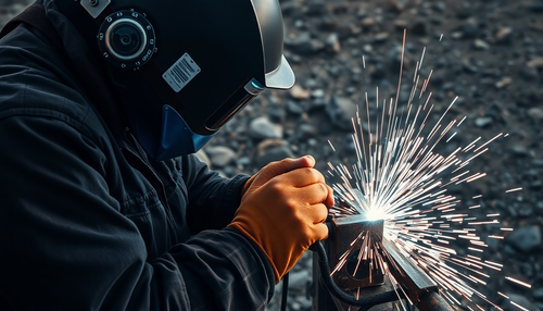
Soldagem em Campo: Desafios e Soluções para Ambientes Adversos
A soldagem é uma técnica essencial em diversos setores industriais, desde a construção civil até a fabricação de equipamentos. No entanto, quando a soldagem precisa ser realizada fora do ambiente c...
-
Soldagem por Arco Submerso: Eficiência e Versatilidade na Indústria
A soldagem por arco submerso (SAW) é uma técnica amplamente utilizada na indústria, conhecida por sua alta taxa de deposição e capacidade de soldar chapas grossas e estruturas pesadas. Este process...
-
A Solda de Tampão: Unindo Chapas com Eficiência e Resistência
A solda de tampão, também conhecida como solda de pino ou solda de ponto, é uma técnica amplamente utilizada na indústria e na construção civil para unir chapas sobrepostas de maneira rápida, efici...
-

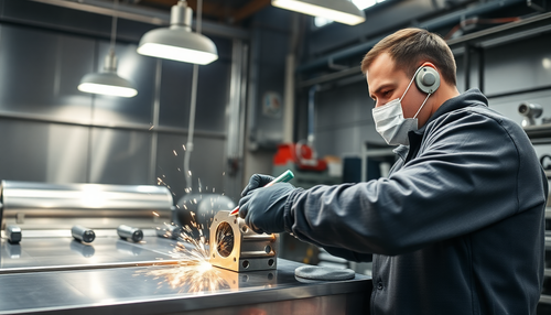
Como obter um Acabamento Perfeito na Solda com Esmerilhamento Correto
Na indústria e construção, o acabamento superficial da solda é um fator crucial para a aparência final e a integridade estrutural de um projeto. Um acabamento mal feito pode comprometer a resistênc...
-
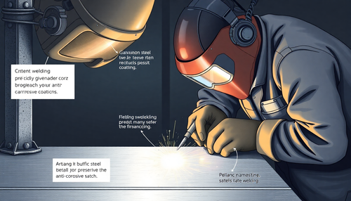
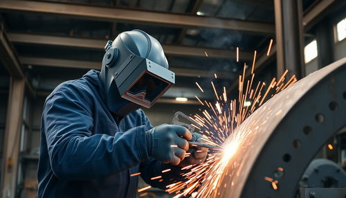
Como Soldar Aço Galvanizado sem comprometer a Proteção Anticorrosiva
A solda é uma técnica essencial na indústria e construção, permitindo a união de peças metálicas de forma segura e eficiente. No entanto, quando se trata de soldar aço galvanizado, existem desafios...
-
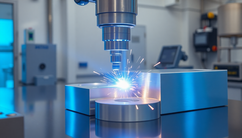
A Soldagem por Feixe de Elétrons: Técnica Avançada para Unir Metais com Precisão
A soldagem por feixe de elétrons (EBW) é uma técnica avançada de união de metais que utiliza um feixe de elétrons acelerados em uma câmara de vácuo para fundir e soldar materiais com precisão milim...
-
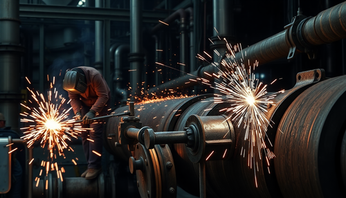
Soldagem em Tubulações: Desafios e Técnicas Essenciais
A soldagem em tubulações é uma tarefa crítica na indústria e construção, exigindo habilidades especializadas e técnicas avançadas. Neste artigo, exploraremos os desafios técnicos envolvidos nesse t...
-
Como o ângulo da tocha afeta a solda MIG
A solda MIG (Soldagem por Gás de Metal) é uma técnica amplamente utilizada na indústria e construção, conhecida por sua eficiência e versatilidade. Um dos fatores-chave que influenciam diretamente ...
-
Soldagem em Alumínio: Principais cuidados e Técnicas Recomendadas
O alumínio é um material amplamente utilizado na indústria e na construção civil devido às suas propriedades únicas, como leveza, resistência à corrosão e alta condutividade elétrica e térmica. No ...
-

Como lidar com Rachaduras na Solda ao Resfriar o Cordão
A soldagem é uma técnica fundamental na indústria e construção, permitindo a união de peças metálicas de forma eficiente e resistente. No entanto, um desafio comum que os profissionais enfrentam é ...


 Welding wire diameter.


