A cam and follower is a method of converting rotary motion into linear motion. The best-known application is in internal combustion engines, where the combination of cam and follower determines the valve opening times and duration. (through the rod and rocker arm).
Other applications may be in industrial machinery, regulating the opening and closing of equipment for filling bottles or containers, toys (for example, a “quacking duck” toy, where a cam can be used to move the duck's beak and make the quacking noise), in fact, any application where you want a fairly short linear motion at regular repeated intervals.
In machines, particularly in typical textile and automatic machines, many parts need to receive different types of movement in a specific direction. This is achieved by converting the available motion into the required motion type. Change from circular motion to translational (linear) motion of simple harmonic type and vice versa and can be done by sliding crank mechanism as discussed earlier. But now the question arises that what to do when the circular or rotary motion has to be transformed into linear motion of complex nature or oscillatory motion. This work is well done by a mechanical part of a mechanical member, known as cam.
 camera types
CAMS Definition:
A cam can be defined as a rotating, reciprocating, or oscillating piece of machinery designed to impart reciprocating, oscillating motion to another mechanical part, called a follower.
A cam and a follower normally have a line contact between them and as such constitute a superior pair. The contact between them is maintained by an external force which is usually provided by a spring or sometimes by the sufficient weight of the follower itself.
Camera classification
Cameras are classified according to:
(a form
(b) Follower movement
(c) Follower restriction type
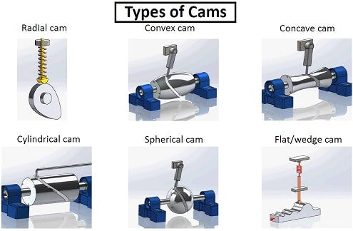
According to the shape
Wedge and flat cameras
It is shown in Figures 1.48 (a), (b), (c) and (d).
In Figure 1.48 (a), when transmitting horizontal translational movement to the wedge, the follower also translates, but vertically in Figure 1.48 (b), the wedge has a curved surface at its top. The follower obtains an oscillatory movement when a horizontal translational movement is given to the wedge. In Figure 1.48(c), the wedge is stationary, the guide receives translational movement within the given constraint. This results in the translational motion of the follower in Figure 1.48 (d). Instead of a wedge, a rectangular block or flat plate with a groove is provided. When horizontal translational motion is transmitted to the block, the follower is required to have a vertical translational motion.
 Types of Wedge Cams
Furthermore, there is no need to provide a spring in this case as in case (a) and (b). In this case, the groove path, which causes the follower to move, restricts the follower to move up and down.
Radial or disk camera
In radial or disc cams, the shape of the working surface (profile) is such that the followers alternate in a plane perpendicular to the cam axis, as shown in Figure 1.49 (a). It is called radial cam because the movement of the followers obtained is radial (Figure 1.49). A differently shaped radial cam is also shown in Figure 1.49(b).
 Types of radial cams
It should be noted that radial cams are very popular due to their simplicity and compactness,
Cylindrical cameras
Cylindrical cams were shown in Figures 1.50 (a) and (b). In Figure 1.50(a), the follower reciprocates, while in Figure 1.50(b) the follower oscillates. Cylindrical cams are also known as barrel or drum cams.
 cylindrical cam
Spiral cameras
This is shown in Figure 1.51. The cam comprises a plate on the face of which a spiral-shaped groove is cut. The spiral groove is provided with teeth that engage the pin gear follower.
This cam has limited use because it needs to reverse its direction to reset the follower position. This camera has found its use in computers.
 spiral camera
Conjugated Cameras
As the name indicates, the cam is composed of two discs, fitted together and remaining in constant contact with two rollers of a follower, as shown in Figure 1.52.
 combined camera
This cam is used where the requirement is high dynamic load, low wear, low noise, high speed and better follower control.
Globoid Cameras
This cam has two types of surfaces: convex and concave . A helical contour is cut into the circumference of the cam's rotating surface, as shown in Figures 1.53 (a) and (b). The end of the follower is made to move along the contour and then oscillatory motion is obtained. In this cam, a large oscillation angle of the follower is obtained.
 Globoid Cameras
Spherical cameras
In this cam, as shown in Figure 1.54, the cam is in the shape of a sphere on the periphery of which a helical groove is cut. The roller provided at the end of the follower rolls in the groove causing oscillatory movement for the follower on an axis perpendicular to the axis of rotation of the cam.
 spherical cam
According to the Follower Movement
Ascension-Return-Ascension (RRR)
In this type of cam, its profile or contour is such that the cam rises, returns without rest or rest, and without any rest or rest, it rises again. The follower displacement and cam angle diagram for this type of cam is shown in Figure 1.55(a).
Housing, Ascension-Return Housing (DRRD)
In this type of cam, after the pause, the follower rises, then it returns to its original position and remains there a few times before rising again. Generally, this type of cam is commonly used. Its displacement cam angle diagram is shown in Figure 1.55 (b).
Dwell-up-dwell-return
It is the most used type of cam. In this, the stay is followed by an ascent. Then the follower remains stationary at the given pause and then returns to its original position (Figure 1.55(c)).
Dwell-up-dwell
As can be seen from the follower displacement versus cam angle diagram shown in Figure 1.55 (d) in this cam, the drop is sudden, which requires a huge amount of force to make it happen.
 types of cam dwell increase dwell
According to the type of follower restriction
Spring Cam preloaded
For its proper functioning, there must be contact between the cam and the follower throughout its operation, and this is achieved using a pre-loaded spring as shown in Figures 1.48 (a) and (b), etc.
Positive drive cam
In this case, contact between the cam and follower is maintained by installing a roller on the operating end of the follower. This roller operates in the groove provided on the cam. The follower cannot exit the groove, as shown in Figures 1.52 to 1.54.
Gravitational Drive Camera
In this type of cam, lift or rise of the follower is achieved by the rising surface of the cam (Figure 1.48 (c)) and the follower returns or falls due to the force of gravity of the follower. These types of cams cannot be trusted due to their uncertain characteristics.
Also Read: Cam and Follower Definition, Types, Naming of Cam
Follower Rating
Followers can be classified in three different ways:
(a) Depending on the type of movement, i.e. reciprocating or oscillating.
(b) Depending on the axis of motion, i.e., radial or displaced.
(c) Depending on the shape of the end in contact with the cam.
Those of followers who fall into classification (a) and (b) have already been treated as indicated above. Type (c) followers will be taken into account now.
Depending on the shape of the end in contact with the cam
Under this classification, followers can be divided into three types:
(a) Razor-edge follower (Figure 1.55 (a))
(b) Roller follower (Figure 1.55 (b))
(c) Flat or mushroom follower (Figure 1.56 (c))
Knife tip follower
Knife edge followers are generally not used due to the obvious high rate of wear on the knife edge. However, cams of any shape can be worked with it. During work, there is considerable lateral thrust between the follower and the guide.
Roll Follower
In place of the knife edge, a roller is provided at the contact end of the follower, hence the name roller follower. Instead of a sliding movement between the contact surface of the follower and the cam, a rolling movement occurs, with the result that the wear rate is greatly reduced. Also in roller followers, as in the knife-edge follower, lateral thrust is exerted on the follower guide. Roller followers are widely used in stationary gas and oil engines. They are also used in aircraft engines due to their limited wear at high cam speeds.
When working on the concave surface of a cam, the surface radius must be at least equal to the roller radius.
Advantages of roller follower over knife edge follower
a) Roller follower has less wear than knife edge follower.
b) Lateral thrust is less compared to knife edge follower.
c) The power required to actuate the cam is lower due to the lower friction force between the cam and the follower
d) The function is smooth
e) Cam-follower arrangement life is longer
f) Undamaged cam surface on roller follower due to bearing
g) No possibility of noise
 types of followers
Flat follower or mushroom
As the name implies, the contact end of the follower is flat, as shown. In mushroom followers, there is no lateral thrust on the guide except due to friction at the contact of the cam and follower. There is no doubt that there will be sliding movement between the follower contact surface and the cam, but wear can be considerably reduced by shifting the axis of the followers, as shown in Figure 1.56(c)(i). The displacement provided causes the follower to rotate about its axis when the cam rotates.
Flat face follower is used where space is limited. This is why it is used to operate car engine valves. Where sufficient space is available, such as in stationary gas and oil engines, the roller follower is used as mentioned above. The flat face follower is generally preferred over the roller follower due to the compulsion of having to use a small pin diameter in the roller follower roller.
In flat followers, high surface tensions are produced on the flat contact surface. To minimize these stresses, the flat end is given a spherical shape, as shown in Figure 1.56(d). Curved or spherical face followers are used in automobile engines.
With flat followers, it is obvious and essential that the cam working surface is convex everywhere.
See more information; Types of cameras and followers – basic machine theory
Cam and Follower Terminology – CAM PARTS
The camera profile
The working contour of a cam that comes into contact with the follower to operate it is known as the cam profile. In Figure 1.57, ABCDA is the cam profile or working contour.
 camera parts
The Base Circle
The smallest circle, drawn from the center of rotation of a cam, that is part of the cam profile, is known as the base circle and its radius is called the smallest radius of the cam. A circle with center O and radius OA forms the base circle. The size of a cam depends on the size of the base circle.
The tracking point
The follower point from which the profile of a cam is determined is called the tracking point. In the case of a knife edge follower, the knife edge itself is the tracking point. In roller followers, the center of the roller is the tracking point.
The tone curve
The location or path of the tracking point is known as the slope curve. On knife-edge followers, the pitch curve itself will be the cam profile. On the roller follower, the cam profile will be determined by subtracting the roller radius radially along the pitch curve.
The Main Circle
The smallest circle drawn on the pitch curve from the center of rotation of the cam is called the leading circle. In knife point followers, the base circle and main circle are the same. In the roller follower, the radius of the parent circle is the radius of the base circle plus the radius of the roller.
The lift or stroke
It is the maximum displacement of the follower in relation to the cam base circle. It is also called camera release. In Figure 1.57, the distance B'B and C'C is the roller follower support.
The angles of ascent, stay, descent and action
- Refer to Figure 1.57, the angle covered by a cam for the follower to rise from its lowest position to the highest position is called ascent angle denoted as θ1.
- The angle covered by the cam during which the follower remains at rest in its highest position is called the dwell angle, denoted by θ2.
- The angle covered by the cam, for the follower to fall from its highest position to the lowest position, is called the descent angle, denoted as θ3.
- The total angle moved by the cam so that the follower returns to its lowest position after the rise, dwell and fall period is called the action angle. It is the sum of θ1, θ2 and θ3.
The pressure angle
The angle included between the normal to the pitch curve at any point and the line of motion of the follower at that point is known as the pressure angle. This angle represents the slope of the cam profile and as such is very important in cam design.
The starting point
The point on the slope curve with the maximum pressure angle is known as the slope point.
The camera angle
It is the cam rotation angle for a given follower displacement.