If the press brake is equipped with a backgauge, it must be mechanically calibrated to the center of the punch and die.
The backgauge is fully calibrated when delivered and any subsequent calibration will only be necessary in the unlikely event that the fingers or backstop bar are forced out of position.
In addition to mechanical calibration, the backgauge must be calibrated with the ETS software before running a program.
I. Checking the alignment of the backstop bar
1. Vertical plane
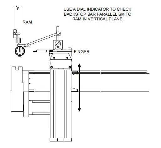
The following procedure can be used to test the parallelism of the backstop bar to the ram in the vertical plane:
1. Mount a magnetic base dial gauge to one of the backgauge fingers.
2. Place the X and R axes in a position that will allow the dial indicator to reference the bottom surface of the ram from the finger.
3. Move your finger to one end of the recoil bar and adjust the dial to zero.
4. Move your finger to the other end of the indicator bar and look at the dial indicator. It should remain at zero.
5. Some crowns are allowed, but the dial indicator must indicate zero at both ends. If necessary, calibrate the anti-rollback bar by completing the procedure outlined in the section below.
2. Horizontal plane
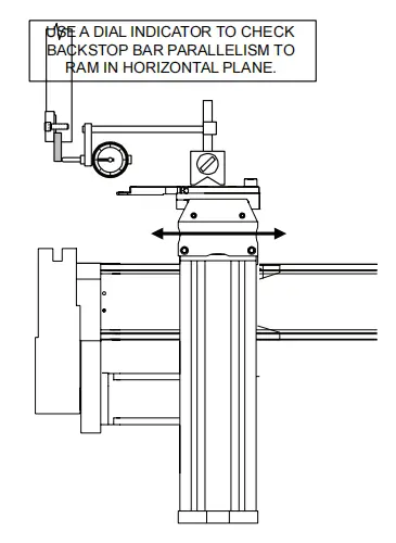
The following procedure can be used to test the parallelism of the backstop bar to the ram in the horizontal plane:
1. Mount a magnetic base dial gauge to one of the backgauge fingers.
2. Place the X and R axes in a position that will allow the dial indicator to reference the back surface of the ram from the finger.
3. Move your finger to one end of the recoil bar and adjust the dial to zero.
4. Move your finger to the other end of the indicator bar and look at the dial indicator. It should remain at zero.
5. If necessary, calibrate the anti-rollback bar by completing the procedure outlined in the section below.
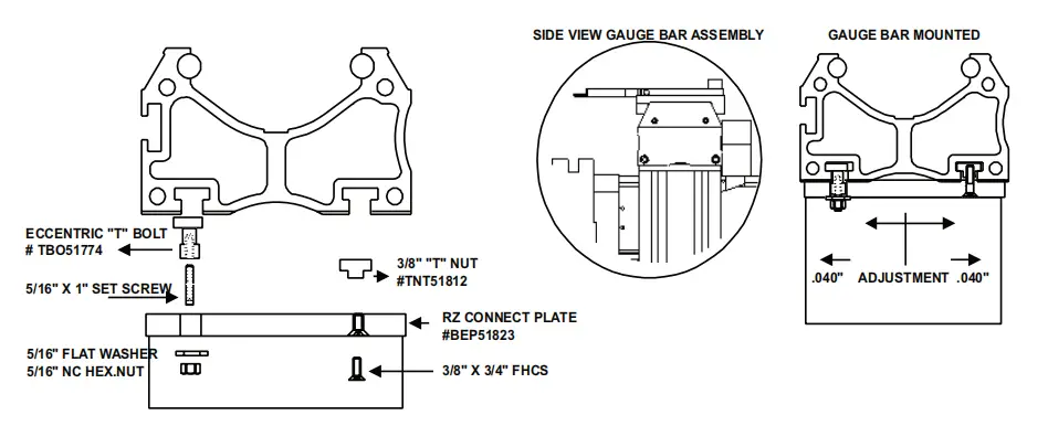
II. Backgauge Calibration Bars
Two calibration bars are provided with the backgauge.
Calibration gauge bars are precision machined steel blocks with a tolerated dimension of 04.000″+0.001″ from the “V” notch to their chamfered end.
Each calibration gauge bar is rubber coated to prevent damage if excessive force is applied when positioning the punch in the “V” notch of the calibration gauge bar.
TO PERCEIVE
Before beginning any of the following mechanical backgauge calibration procedures:
- The operator must be fully familiar with the press brake controls and program execution
- The punch and die must have been installed and centered according to the procedures outlined in the section below.
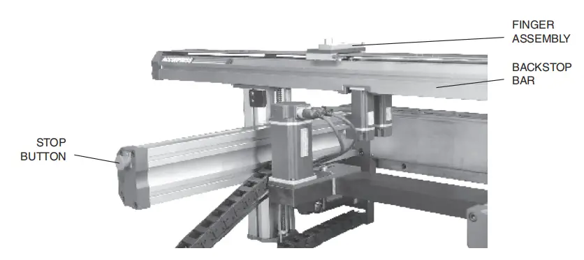
III. Finger Calibration
Backgauge fingers must be calibrated whenever they are out of parallel alignment with the tooling.
If the backstop bar is moved, both the backstop bar and fingers will need to be calibrated. It is good practice to recalibrate the fingers whenever the tool is changed.
This procedure will ensure that both fingers are the same distance from the anti-rollback bar:
1. Set the operation mode to JOG and the control mode to HAND.
2. Run “Calibrate Back Gauge” from the main menu or program and then move the backgauge to the calibration position X=04.000″.
3. Place two calibration bars in the die opening, several centimeters apart and close to the center of the punch length. Each bar must be placed so that the rubber base is in the die and the beveled end faces the backgauge.
4. Using the palm buttons, move the pressure ram down until the punch engages each bar on the calibration gauge
“V” notch, with just enough force applied to slightly deform the rubber support. Check that the calibration meter bar is securely attached by trying to move it manually.
5. Adjust the carriage vertically until the fingers are at the same height as the calibration gauge bars.
The mechanical adjustment of the backgauge takes place behind the press brake. Therefore, for safety reasons, the backgauge STOP button must be pressed and held in its locked position before working in the backgauge area.
For machines with Manual-R system, use the steering wheel of the backrest carriage.
For machines with Power-R system, program the appropriate position.
6. Move a finger from the back gauge to the end of a bar on the calibration gauge. On a Manual-Z system, loosen the carriage clamp and slide your finger. On a Power-Z system, program the appropriate position.
Adjust the finger to the calibration position:
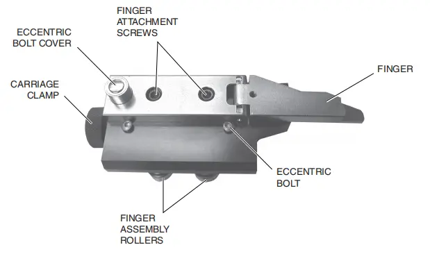
- Using a 5/16″ hex wrench, loosen the two Allen screws securing the finger to the finger block.
- Remove the steel cap from the boss that surrounds the eccentric screw on the back of the finger.
- Using a 7/16″ hex wrench, turn the eccentric screw to fit the finger firmly against the calibration block. Use light pressure with your hand to keep your finger parallel to the edge of the finger pad.
7. Move the second rear gauge finger to the end of the second calibration gauge bar and adjust as described in step 6.
8. Adjust each finger so that the contact pressure between the finger and the indicator bars is the same for both fingers.
9. When adjustment is complete, replace the eccentric screw cover and retighten the two screws.
10. Remove the calibration gauge bars and reactivate the backgauge by turning the backgauge stop knob 1/4 turn clockwise.
4. Recoil bar calibration
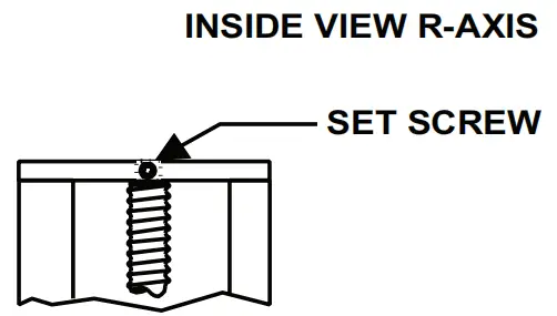
1. Vertical plane
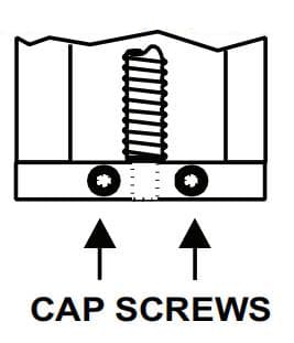
To adjust the anti-rollback bar in the vertical plane, begin by loosening the set screw on the R-axis top plate.
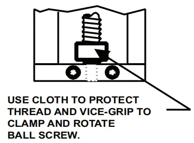
Place a small cloth around the lowest point of the ball screw and apply pliers over the cloth, being careful not to pinch or damage the ball screw.
Loosen the screws on the R-axis bottom plate and turn the ball screw to adjust the height.
When adjustment is complete, tighten the set screw and set screws. Remove the vice-grip
pliers and cloth.
Recoil Bar R-Axis Adjustment
To adjust the height of the R axis, loosen the fixing screw (top plate).
Place a small cloth around the lowest point of the ball screw and apply pliers over the cloth, tight enough to hold the ball screw.
Loosen the screws (bottom plate) and turn the ball screw to adjust the height.
When adjustment is complete, tighten the set screw and set screws.
Remove the pliers and cloth.
2. Horizontal plane
To adjust the backstop bar in the horizontal plane, loosen the T-nuts and turn the T-bolts until parallelism with the ram is achieved.