1. Introduction
In the production of boilers and pressure vessels, the use of roll bending technology is widespread. It includes cylindrical and conical roller bending, as well as a variety of steel section roller bending, with cylindrical tube section roller bending being the most common.
Sheet metal is used to form these parts and they can be made using the pressing or roll bending method, also known as rolling plate. The pressing method typically uses a universal die, while a roll bending machine is used to perform continuous three-point bending on the plate, causing plastic deformation to achieve the required bending radius.
2. Roll folding
Roll bending is a bending forming method in which a roll bending machine is used to bend a sheet metal or profile blank. Shapes that can be obtained through roll bending include cylindrical, conical and variable curvature.
For parts with equal thickness and varying thickness in the thickness direction, a three-roll sheet metal bending machine is typically used. Roll-bent parts made of profiles, such as angled or T-shaped profiles, can have equal curvature or variable curvature. Blanks used in roll bending can be extruded or bent from plates. To bend parts with variable curvature, a four-roll plate bending machine is typically used.
2.1 R is okay to double features
When rolling, the sheet material is positioned between the upper and lower roller shafts of the roller bed. The upper roller axis then descends, causing the plate material to bend and deform due to the bending moment. The rotation of the upper and lower roller axes creates friction between the roller axis and the steel plate, which causes the plate to move, continuously changing the pressure position of the metal sheet and forming a smooth curvature surface, completing thus the profiling process.
During roll bending, the sheet metal undergoes deformation equivalent to free bending. The curvature of the roll-bent part is determined by the position of the rolls, the thickness of the sheet metal and its mechanical properties. By adjusting the relative position between the rollers, the blank can be bent into any curvature smaller than the curvature of the upper roller. However, due to the elastic recovery of bending, the curvature of the part bent by the roller cannot be the same as that of the upper roller.
One of the main advantages of the profiling method is its versatility. Generally, there is no need to add any additional process equipment to the plate rolling mill. Only rolls suitable for different section shapes and sizes are required for profile roll bending. However, the method also has some disadvantages, including low productivity and low accuracy.
2.2 Delayed launch
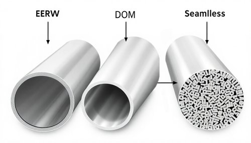
Roll bending machines come in two forms: plate roll and steel roll bending machine. Most of the materials processed using roll bending are raw plates, so the plate roll is mainly used. There are three main types of plate rolling machines: three-roll symmetric plate roller, three-roll asymmetric plate roller and four-roll plate roller.
2.3 R oll bending process
The main method of rolling and bending in a plate roll is to roll a cylindrical surface using a blank plate. With the adoption of appropriate technological measures and necessary equipment, it is possible to roll conical surfaces and also profile steel for roll bending.

The rolling of steel sheets consists of three stages: pre-bending (pressing head), centering and roll bending.
1) Pre-bending
It can be seen in Figure 1 that only a portion of the steel plate that comes into contact with the upper roller axis can undergo bending. As a result, there will be a length at both ends of the steel plate that cannot be bent. This length is called the residual ruler.
The size of the residual ruler depends on the way the equipment is folded. The theoretical value of the residual straightener is shown in Table 1. Typically, the actual residual straightedge is greater than the theoretical value, with values ranging from 6-20t for symmetrical bending and 1/10-1/6 for asymmetrical bending.
Table 1 Theoretical residual limit value of steel plate bending
| Kind of equipment | Plate laminating machine | Press | |||
|---|---|---|---|---|---|
| Bending form | Symmetrical flexion | Asymmetrical flexion | Die doubling | ||
| Three rollers | Four rollers | ||||
| Remaining straight edge | Cold bending | L/2 | (1.5~2)t | (1~2)t | 1.0t |
| Hot bend | L/2 | (1.3~1.5) t | (0.75~1)t | 0.5 tons | |
Note: In the table, L is the center distance of the side roller of the plate bending machine and t is the thickness of the steel plate.
- The general die is used for multiple bending in the press.
It is shown in Fig. 1 (a).
This method is suitable for pre-bending steel plates of various thicknesses.
- Pre-bending with three-roll calender formwork.
It is shown in Fig. 1 (b).
This method is suitable for t≤t0/2, t≤24mm, which does not exceed 60% of the equipment capacity.
- Pre-bending must be carried out on the three-roll bending machine with backing plate and damping block.
As shown in Figure 1 (c).
This method is suitable for t≤t0/2, t≤24 mm, which does not exceed 60% of the equipment capacity.
- Pre-bending with padded block in a three-roll calender.
It is shown in Fig. 1 (d).
This method is suitable for thin steel sheets, but its operation is more complicated and rarely used.
2) Centralization
The purpose of centering is to align the centerline of the part parallel to the roll axis, eliminate the possibility of twisting, and maintain the precise geometric shape of the part after roll bending.
Centering techniques include: side roller centering, special baffle centering, inclined feed centering, and side roll groove centering, as illustrated in Figure 2.

3) Roll folding
Roll bending of steel sheets is generally performed on a rolling machine.
Typical rolling parts are cylindrical and conical.
The. Roll bending for cylindrical parts
When bending the cylinder in a symmetrical three-roll bending machine, the position of the upper roll axis during final bending can be determined according to the known bending radius, as shown in Fig.

Where:
- h – vertical central distance between the upper roller and the side roller, mm
- R – radius of curvature of the part, mm
- t – thickness of the steel sheet, mm
- R 1 – radius of the upper roller axis, mm
- R 2 – radius of the side roller axis, mm
- l 2 – distance from the center of the side roller, mm

The end bending position of the side roll shaft is shown in Fig. 3(b) when the cylindrical surface is rolled on a four-roll sheet metal bending machine, which can be obtained by the following formula:

Where:
- h – vertical central distance between the side roller and the bottom roller, mm
- R – radius of curvature of the part, mm
- t – thickness of the steel sheet, mm
- R 1 – radius of the upper and lower roller axes, mm
- R'- R+t, mm
- l 2 – distance from the center of the side roller, mm
Due to the springback of the metal sheet, the H value obtained in the above formula needs to be corrected appropriately in practical application.
B. Conical surface roll bending:
The commonly used taper roller bending methods are small-mouth deceleration method, double-speed four-roller bending method, rotary feeding method and zone rolling bending method.
This is due to the fact that the main lines on the cone surface are not parallel and the curvature of each point on the main line is unique.
To ensure that the upper roller is always pressing against the centerline of the cone during the bending process and to produce different radii of curvature along the centerline, the following measures must be taken:
- Adjust the position of the upper roller so that it is tilted at a specific angle to the lower roller.
- Maintain the proximity of the top roller to the cone surface line by implementing unequal feed rates at both ends of the cone.
For tapered parts with large taper, the vertical center distances, Ya and Yb, of the upper and lower rollers at both ends can be calculated using the geometric figure shown in Figure 4.
The central distances, Ya and Yb, of the upper and lower rolls can be obtained by applying the calculation method for simple circular parts, that is, using formula (1).
From the geometric figures presented in Figures 4 (b) and 4 (c), the following values can be obtained:

The position of the blank at the right end of the roll is determined by l b +c, where

For conical parts with small taper, equation (2) can be simplified as follows:

When rolling tapered parts, distortion is common.
An effective method to eliminate this distortion is to reasonably tilt the upper roller and maintain parallel alignment of the lower roller.
During the rolling and bending process, the blank is formed through a series of overlapping sectional bends.
2.4P roll bending process classification
According to the different temperatures of the laminating plate, it can be divided into cold rolling, hot rolling and medium rolling.
1) Cold rolling
Rolling a board at normal temperature, also known as cold rolling, is suitable for rolling thin to medium-sized boards.
However, this results in a certain amount of springback, as demonstrated in Figure 5.
Once the desired flexion is achieved, it is necessary to reverse several times to fix the curvature.
High-strength steel has a high degree of springback. To reduce springback, it is advisable to carry out annealing treatment before the final forming process.
The minimum diameter of a cylinder that can be bent using the press brake depends on the diameter of the upper roll.
Taking into account the springback of the cylinder after bending, the minimum diameter of a collapsible cylinder is approximately 1.1 to 1.2 times the diameter of the upper roller.
Cold rolling is a convenient process with easy-to-control curvatures and low production costs. However, it requires powerful equipment for thicker sheets and is susceptible to the development of cold work hardening.

2) Hot rolling
It is generally considered that when the thickness