Practical calculation of bearing life
Previously, we discussed how to calculate the life of a bearing. In these articles, we mainly introduce the theoretical aspects of bearing service life and calculation formula.
Today, we intend to apply this theory to practical scenarios. After all, the ultimate goal of acquiring theoretical knowledge is to meet practical engineering needs. Some engineers have requested real-world calculation examples, so let's dive deeper using the example from our previous article.

Let's revisit the vertical engine example. Here are the relevant bearing details:
- Bearing Model: 6208
- Basic bearing dynamic load rating: 29kN
- Equivalent dynamic bearing load: P=5.83kN
We will also provide some additional parameters for this bearing:
Bearing speed: n = 1500 rpm
Using the Bearing Life Formula we obtain the bearing life:
Here, p is the bearing calculation coefficient. When the rolling element of the bearing is a ball, p is 3, and when the rolling element is a roller, p is 10/3. The resulting bearing life is 123.08, in millions of revolutions. Converting to a more common unit of time, we obtain:
The calculated bearing life is approximately 1,368 hours.
In this example, we use a scenario where the bearing is under a high load. The calculated result suggests that the bearing is not suitable for this application due to its short service life. If the motor operates continuously, the basic rating life can only guarantee less than two months of bearing operation.
In other words, if we choose this bearing, we can only guarantee that 90% of the bearings will be able to operate continuously for two months under these conditions.
The above value is the bearing life value obtained using the basic bearing life theory.
However, as you may have noticed, as in our previous articles, the entire calculation process only considers the bearing load. In other words, the so-called bearing life only considers the impact of the load. As we discussed in our previous articles, after many years of developing modern bearing life theory, this calculation no longer meets our needs. Therefore, we need to adjust this value further.
In other words, we need to calculate the modified life value of the bearing. Most subsequent calculations do not use standardized methods because these calculations can be complex, many of the reference processes or theories come from experiments, and thirdly, various bearing suppliers and international bearing standards have provided us with a better reference tool: the graphics. So how do we use these charts? Let's explore this using our example.
Adjusted bearing life
As described in our previous articles, the formula for adjusted life is as follows:
To determine the final value L 10mh we need to define a1 and a iso .
01 First we define a1.
As we discussed earlier, a1 is known as the adjusted life reliability coefficient. When reliability is 90%, the value of a1 is 1. For general-purpose machines used in industry, unless specifically required, bearing life is always based on 90% reliability. So in this example, we can directly take a1.
02 Secondly, we find an iso .
The standard method for calculating the iso- adjusted life coefficient of a bearing considers the following factors:
- Bearing load
- Lubrication conditions (lubricant type and viscosity, speed, bearing size, whether additives are used)
- Bearing Fatigue Limit
- Bearing type
- Bearing residual stress
- Environmental conditions
- Contamination in the lubricant
In summary, an iso is a function of the following parameters:
Where:
- η c is the bearing contamination factor,
- C u is the fatigue load limit of the bearing,
- k is the viscosity rate of the bearing lubricant.
First, we select the bearing contamination factor ηc. In ISO281 and in all bearing manufacturers' catalogues, there is a reference table for selection criteria as follows:
| Pollution | EC coefficient | |
| dm<100 mm 1 ) | dm≥100mm 1 ) | |
| Extremely clean -Particle size smaller than the thickness of the oil film -Laboratory conditions |
1 | 1 |
| Highly clean -Oil filtered by ultra-fine filters -Bearings lubricated with sealed grease |
0.8-0.6 | 0.9-0.8 |
| Standard cleaning -Oil filtered by fine mesh filters |
0.6-0.5 | 0.8-0.6 |
| Light pollution -Slight contamination of the lubricating oil |
0.5-0.3 | 0.6-0.4 |
| General pollution -Contamination of bearings by abrasive particles in other mechanical parts |
0.3-0.1 | 0.4-0.2 |
| Severe pollution -The environment in which the bearing is used is seriously polluted -Poor bearing sealing arrangement |
0.1-0 | 0.1-0 |
| Extreme pollution | 0 | 0 |
In the application of vertical motors, based on our past experience, the bearing contamination factor should be selected between light pollution and general cleanliness. In this case, we chose a contamination factor of 0.6, which is slightly higher than general cleaning.
Let me add,
Contamination factor selection does not have a specific mathematical formula to refer to. It generally depends on years of experience in bearing applications. The more applications we find, the more insights we gain in this selection.
As the selected bearing is 6208, the fatigue load limit C of this bearing can be found in the bearing catalog as: 1.05kN
The value of the equivalent dynamic load of the bearing was calculated in the previous chapter as P=5.83kN
Therefore, we can obtain an approximate value:
Next, we need to make a slightly more complex choice of the viscosity ratio k. Due to limited space in this chapter, we will not go into detail about the specific meaning of k and how to choose this value. We will write another article to detail it later. For now, we just want to emphasize that for bearings, choosing the correct lubrication is very important. This not only refers to the quality of the grease itself, but also the impact of lubrication on the bearings.
Regarding the viscosity ratio,
Generally, we expect that the chosen final lubrication value of k can be selected between 1 and 4, with several considerations.
If the calculated k value of the selected lubrication value is:
- Less than 1 means that the lubrication did not achieve the desired effect. The purpose of a lubricant is to separate the steel-to-steel contact between the bearing race and the rolling element. If k<1, it indicates that the lubricant has not separated the steel-steel contact and the bearing will still generate friction during operation.
- Greater than 4 means too much lubricant has been added. Although it perfectly separates the metallic contact, excess lubricant in the bearing will generate what we call “drag loss” torque. This is a very important part of the bearing friction model. In layman's terms, the main purpose of lubrication is to reduce friction and further lower the temperature of the bearing. However, too much lubricant can also create “friction,” which will also generate heat.
Therefore, we select a suitable lubrication value and the final k value is 1.5.
With these two parameters, we can find the following chart in ISO281 or in the bearing manufacturer's catalog.
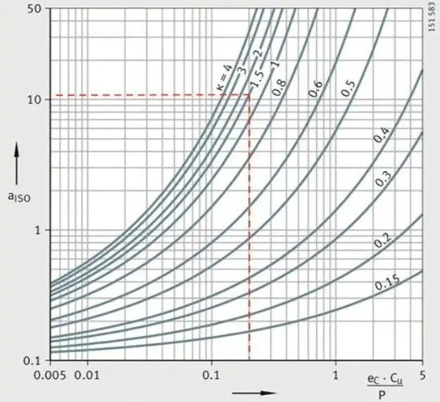 ISO life correction coefficient for radial ball bearings
Careful!
There are several similar diagrams, each for different types of bearings. We choose deep groove ball bearing, which is a kind of radial ball bearing. Therefore, select the appropriate chart based on the specific bearing type.
From the chosen diagram, we can determine that, in this application, aiso=12.
In this example, the final corrected rating life of the 6208 bearing is:
l 10mh = a 1 ×a iso ×L 10h = 1×12×1367.6 = 16411.2
In this vertical engine, under adequate lubrication conditions, the bearing can operate for 16,410 hours.
Purpose of the calculation
Since the bearing life calculation result cannot accurately reflect the actual bearing life, what is the purpose of this calculation?
In fact, many engineers misinterpret service life calculation as “guesswork,” likely due to its name. Originally, the objective of studying the fatigue life of bearings was to establish a reference value, a useful life reference. Over time, this reference value has become a parameter to compare and verify the reasonableness of bearing selection.
In fact, the bearing life calculation is a check of the load capacity of the chosen bearing. In other words, it's about choosing the smallest bearing that can meet the service life requirements. In this sense, the calculation of the bearing life is a requirement for the lower limit of the bearing's load capacity.
How can we understand this? Let's start with the health check process:
When engineers check bearing life, mechanical design manuals and equipment materials always provide some minimum values for service life requirements. The following is an example:
| Operating Conditions: | Types of machines | Required bearing life (time, h) |
| Short-term or intermittent operation | Household appliances and power tools, agricultural machinery, winches. | 4,000 ~ 8,000 |
| Infrequent use, but reliable operation required | Domestic air conditioning units, construction machines, belt conveyors, elevators. | 8,000 ~ 12,000 |
| Not continuous, but prolonged operation | Roller necks of rolling mills, small electric motors, cranes. | 8,000 ~ 12,000 |
| Electric motors in general, gear devices in general. | 12,000 ~ 20,000 | |
| Machine tools, vibrating screens, crushers. | 20,000 ~ 30,000 | |
| Compressors, pumps, crucial gear devices. | 40,000 ~ 60,000 | |
| Constant operation exceeding 8 hours daily or long-term continuous operation | Escalator. | 12,000 ~ 20,000 |
| Centrifugal separators, air conditioning equipment, blowers, woodworking machines, railway vehicle axles. | 20,000 ~ 30,000 | |
| Large electric motors, mine winches, main electric motors for railway vehicles, locomotive axles. | 40,000 ~ 60,000 | |
| Papermaking machines. | 100,000 ~ 200,000 | |
| Uninterrupted and faultless operation 24 hours a day | Water supply equipment, power plant equipment, mining drainage equipment. | 100,000 ~ 200,000 |
Of course, some equipment manufacturers offer different service life requirements. Often these service life values are met by bearings in traditional designs.
Therefore, when designing new equipment and checking bearing life, the following approach can be used:
- If the service life of the newly chosen bearing is less than the required service life: The load capacity (and corresponding service life under this load) of the selected bearing is less than that of bearings that previously satisfied this condition. In other words, the bearing chosen is too small;
- If the calculated service life of the newly chosen bearing is greater than or equal to the required service life: The load capacity (and corresponding service life under this load) of the selected bearing is greater than that of bearings that previously satisfied this condition. In other words, the chosen bearing is too large;
The choice of too small or too large should be within a reasonable range and absolute equality should not be sought. Therefore, when looking at the “required service life”, we would find that this value is a range, not an absolute.
Therefore, the implicit calculation of bearing life involves checking the load capacity of the bearing under reasonable service life requirements. In other words, choose a bearing of reasonable size under certain working conditions.
In real life, due to misunderstanding of the above concepts, many “operation errors” occur:
(1) The calculated service life of a bearing must meet the equipment warranty period.
This practice confuses checking the bearing load with the useful life of the equipment. In fact, checking the useful life of a bearing is not equivalent to “fortune telling”, as explained in the previous article.
Actual bearing conditions are varied and engineers cannot calculate each machine individually. This is a misunderstanding on the part of equipment manufacturers about “bearing life calculation”.
The concept of warranty period places all responsibility on the equipment manufacturer, a “warranty” concept that is much broader than the concept covered by “bearing life calculation”, making such a direct application inappropriate.
Of course, some engineers, due to customer pressure, are forced to meet a “20 year” service life requirement. Under such a mandate, the bearings chosen are often oversized, which not only results in economic inefficiency, but also misunderstands that larger or longer service life calculations are not always better for the bearings.
(2) The longer the calculated life of a bearing, the better it will sound.
In fact, this also confuses bearing selection. As I mentioned earlier, the bearing life check calculation is a check of the minimum load capacity of the bearings under working conditions.
On the other hand, there should also be a limit to the maximum load capacity of bearings, which is the upper limit of the load capacity of bearings under working conditions. If the calculation result exceeds this value, problems with the bearing will occur.
This is what we often call “minimum bearing load”. If the bearing chosen is too large and the calculated service life of the bearing under working conditions is long, which means that the load capacity of the bearing is too high, it may not meet the minimum load requirement of the bearing.
If the load supported by the bearing is less than the minimum required load, problems such as rolling element slippage may occur within the bearing, making it more prone to burning.
In fact, understanding the concept of bearing life can lead to numerous design optimizations. These include:
Evaluate whether it is possible to reduce bearing size and at the same time meet service life requirements;
Keep a record of the life of various bearings and consider further size reductions if there is any consistent residual life.
In summary, in engineering practice, bearing life calculation is used to verify the bearing's load capacity, not simply to maximize it. Furthermore, this calculated life does not reflect the “true” bearing life.
An accurate understanding of bearing life concepts assists in the correct selection of bearing sizes.
Unfortunately, in real work, we sometimes have to submit to our clients' demands, even if we believe their requests are technically unreasonable. So feel free to share this article with them.
This might be the most challenging article to understand on the site so far, especially for electrical engineers. If anyone has any questions, feel free to leave a comment for discussion.